Heltec v4 I2C pins

Hello everyone,
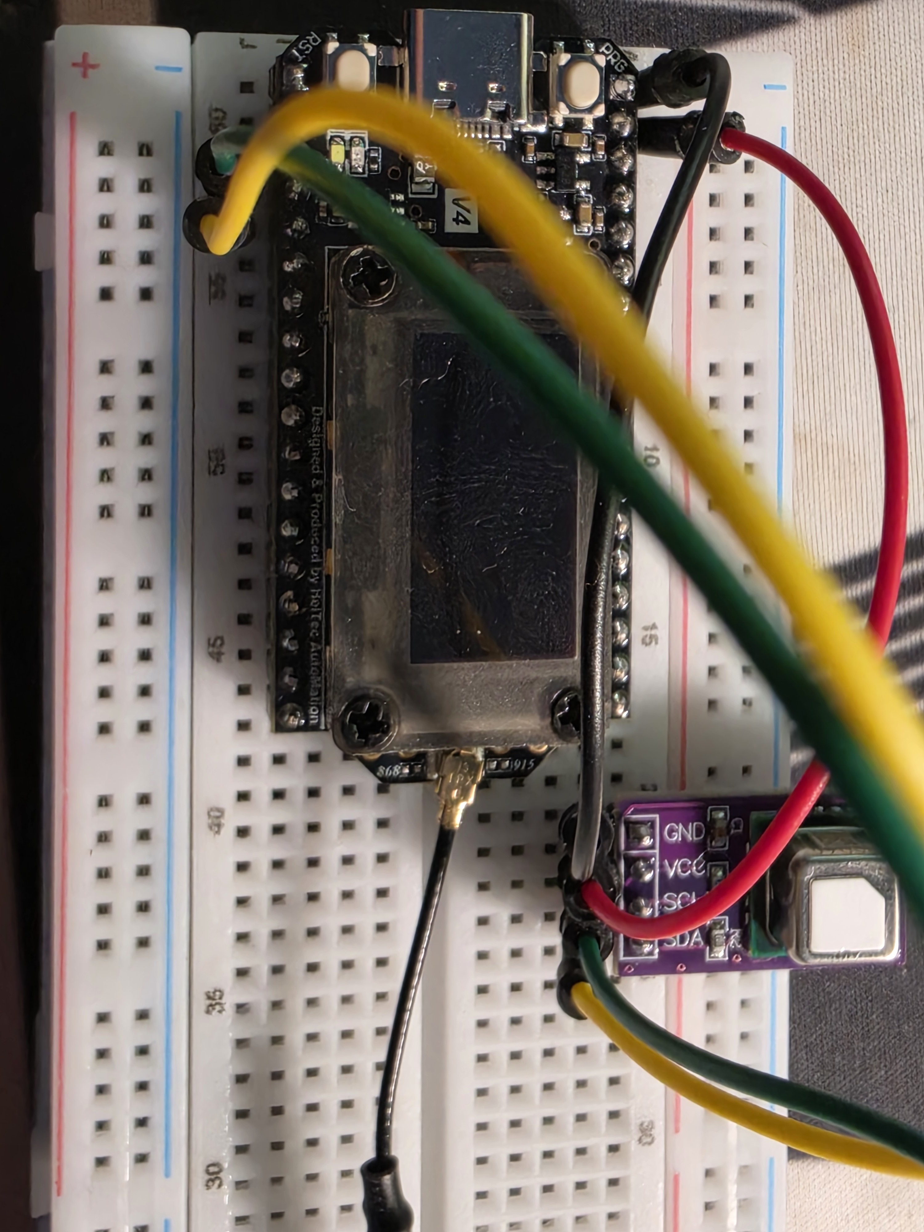
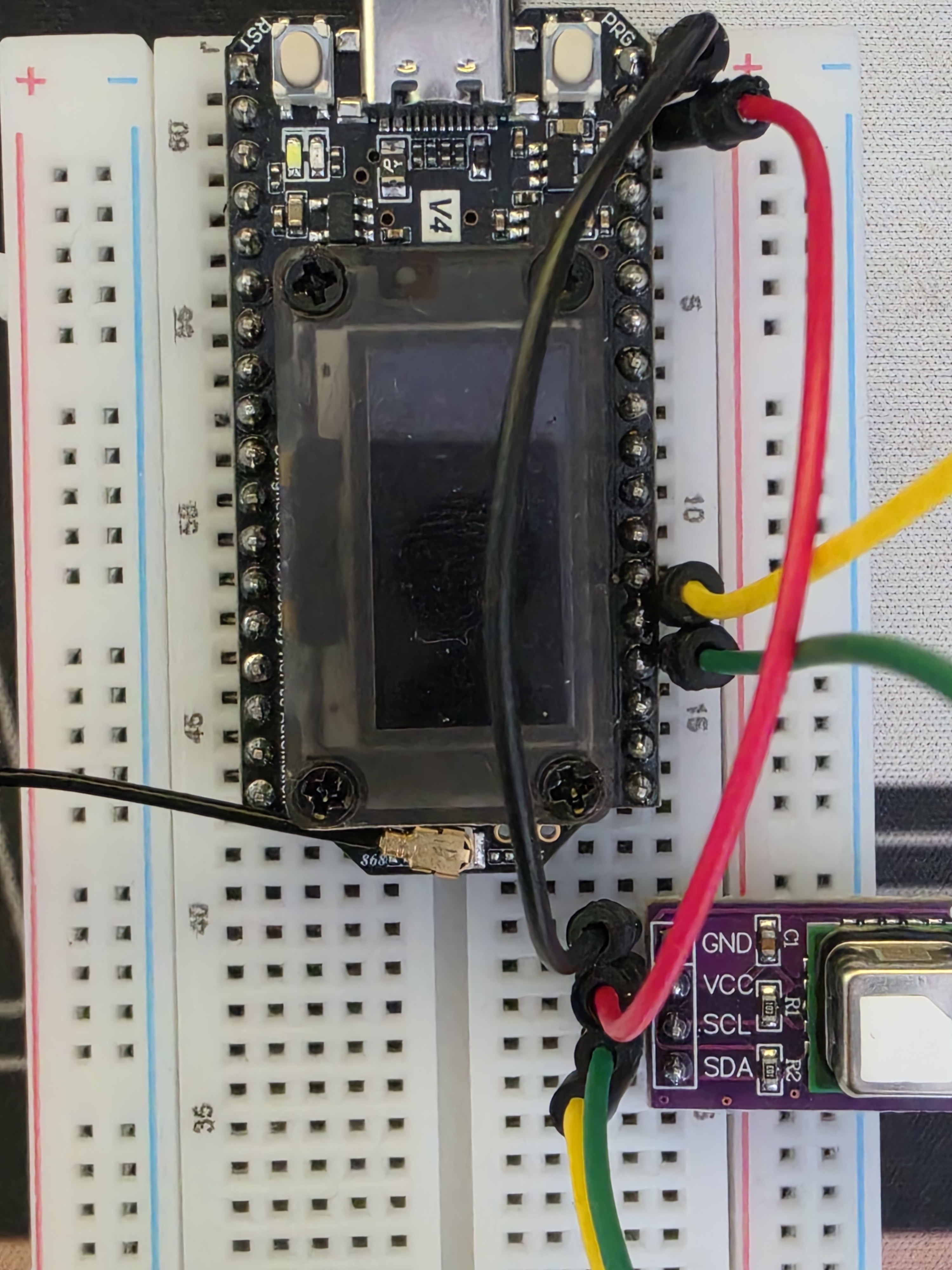
Can someone help me figure out how to connect a scd40 sensor the the heltec V4?
I tried using an I2C scanner but it does not pick up my sensor, so I’m guessing that I am initialising the second bus incorrectly or using the wrong GPIO pins. I don’t want to use pins 17/18 that the OLED screen uses since I did not solder them on (don’t have a soldering kit at home).

Any help is appreciated, thank you!

You may be very close, so if you share what you used for your scanner and what you wired up we may spot the detail. You get much more satisfaction from fixing your own code than copying someone else’s :slight_smile:

This comes up for the v3 as well! Have you searched the forum?

This is the code for the Arduino sketch. Although I care more about ESP-IDF, but anyway this is the the libraries example “I2C_Scanner”. I uncommented what was needed here and I also tried various other scanners I found online with every possible combination of SDA/SCL pins I could find. I attached the wiring photo.


Here is my code that I actually want to be able to run.:

It’s a bit hard to see with that picture, but it looks like SDA is connected to GPIO43 and SCL is connected to GPIO44? In that case, it should be enough to use Wire.begin(43, 44). The code itself otherwise looks good as does the wiring for GND and VCC.
If you want to use Wire1, simply swap all Wire use to Wire1, not much else to get excited about.
The only conflict I could think of is that Serial is routed over 43/44 but I think you are using USB CDC? In that case 43 and 44 should be good. But could be useful to try GPIO5 and GPIO6 or so instead.

(There are very few of us here with experience in ESP-IDF.)

If that’s still a problem, I’m using GPIO41/GPIO42 successfully. The pins_arduino.h file has SDA/SCL defined as pins GPIO3/GPIO4, so they should also work. As you note, GPIO43/GPIO44 are defined as TX/RX in the pins_arduino.h file so, even though the V4 is using the USB CDC, the module may already be doing something with those pins.

EDIT: Actually, looking more closely at your photo, are you using GPIO3/GPIO4, which are actually on the pins that are numbered J3-14/15 on the pinout diagram (on the same side of the board, up towards the other end, as your power supply pins), or pins J2-3/4, which are actually Ve pins…?

Turn out I was actually using the Ve pins… Thank you everyone for the help, especially Pete haha. Can’t believe I didnt realise this after switching the pins so much. The thought that I spent hours trying to debug everything…
I attached a photo of how it looks now in case someone is interested.