Heltec Lora 32 v3 hardware Serial?

I am working on a project and I have been stuck for a week, I am trying to do serial communication between the Heltec Lora 32 v3 and M6E nano RFID module using hardware serial so that the RFID reader can detect tag. The Heltec lora 32 V3 it says 3* UART where are those pins? Also what is the right way to initialize them dor serial communication.

Link to the RFID reader M6E nano with documents:

Here is the pin diagram for Heltec lora 32 v3

Please kindly let me know.

If you look at the Espressif docs for the MCU it will tell you which pins you can use for hardware serial and then map that over to the v3 pinout.

I think this is correct from ESP32 S3 series documentation:

Pin Assignment
• UART0
– The pins U0TXD and U0RXD that are connected to transmit and receive signals are multiplexed with
GPIO43 ~ GPIO44 via IO MUX, and can also be connected to any GPIO via the GPIO Matrix.
– The pins U0RTS and U0CTS that are connected to hardware flow control signals are multiplexed
with GPIO15 ~ GPIO16, RTC_GPIO15 ~ RTC_GPIO16, XTAL_32K_P and XTAL_32K_N, and SAR ADC2
interface via IO MUX, and can also be connected to any GPIO via the GPIO Matrix.
Espressif Systems 48
Submit Documentation Feedback
ESP32-S3 Series Datasheet v2.0
4 Functional Description
– The pins U0DTR and U0DSR that are connected to hardware flow control signals can be chosen
from any GPIO via the GPIO Matrix.
• UART1
– The pins U1TXD and U1RXD that are connected to transmit and receive signals are multiplexed with
GPIO17 ~ GPIO18, RTC_GPIO17 ~ RTC_GPIO18, and SAR ADC2 interface via IO MUX, and can also be
connected to any GPIO via the GPIO Matrix.
– The pins U1RTS and U1CTS that are connected to hardware flow control signals are multiplexed with
GPIO19 ~ GPIO20, RTC_GPIO19 ~ RTC_GPIO20, USB_D- and USB_D+ pins, and SAR ADC2 interface
via IO MUX, and can also be connected to any GPIO via the GPIO Matrix.
– The pins U1DTR and U1DSR that are connected to hardware flow control signals can be chosen
from any GPIO via the GPIO Matrix.
• UART2: The pins used can be chosen from any GPIO via the GPIO Matrix.
For more information about the pin assignment, see Section 2.3 IO Pins and
ESP32-S3 Technical Reference Manual > Chapter IO MUX and GPIO Matrix

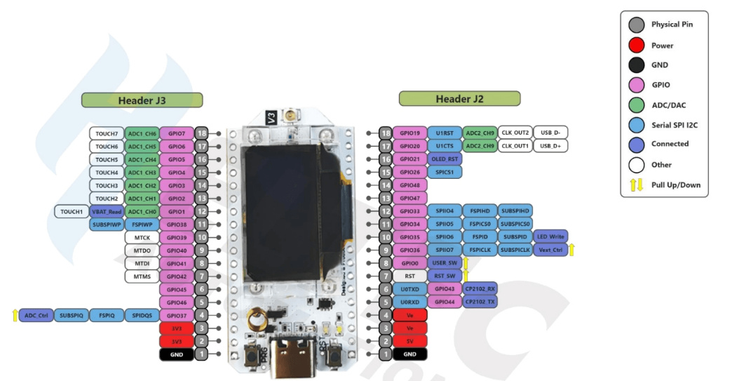
I used GPIO39 and GPIO40 in the following test code on the Heltec LoRa 32 V3

// Heltec ESP32S3 LoRa  V3  Serial1 test - for loopback test connect pin GPIO40 U1TXD to pin GPIO39 U1RXD"

#define RXD1 39
#define TXD1 40

void setup() {
  // initialize both serial ports:
  Serial.begin(115200);
  Serial1.begin(9600, SERIAL_8N1, RXD1, TXD1);
  Serial.println();
  Serial.printf("\n\nHeltec ESP32S3 LoRa  V3 serial1  test pin GPIO%d U1RXD pin GPIO%d U1TXD\n", RXD1, TXD1);
  Serial.printf("   for loopback test connect pin GPIO%d U1RXD to pin GPIO%d U1TXD\n", RXD1, TXD1);
  Serial.printf("RS232: ESP32S3 GPIO%d RXD1 to TTL/RS232 Rx and GPIO%d TXD1 to TTL/RS232 Tx\n", RXD1, TXD1);
  Serial.printf("RS232 - loopback connect 9-pin D-type pin 2 Tx to pin 3 Rx\n");
}

void loop() {
  // read from port 1, send to port 0:
  if (Serial1.available()) {
    int inByte = Serial1.read();
    Serial.write(inByte);
  }

  // read from port 0, send to port 1:
  if (Serial.available()) {
    int inByte = Serial.read();
    //Serial.write(inByte);
    Serial1.write(inByte);
  }
}

connecting GPIO39 to GPIO40 to form a loopback the Arduyino IDE serial monitor displays

Heltec ESP32S3 LoRa  V3 serial1  test pin GPIO39 U1RXD pin GPIO40 U1TXD
   for loopback test connect pin GPIO39 U1RXD to pin GPIO40 U1TXD
RS232: ESP32S3 GPIO39 RXD1 to TTL/RS232 Rx and GPIO40 TXD1 to TTL/RS232 Tx
RS232 - loopback connect 9-pin D-type pin 2 Tx to pin 3 Rx
loopback test 1
loopback test 2 123445676890