FEATURE REQUEST for power management

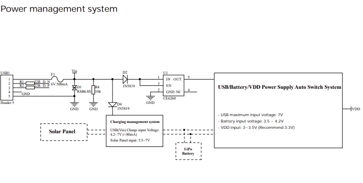
Due to how the charging/power management/power switching is implemented on the CubeCell boards, I am unable to determine the following:

-When is it on external power (USB)
-When is it charging. I need this to compensate for self-heating during charging.

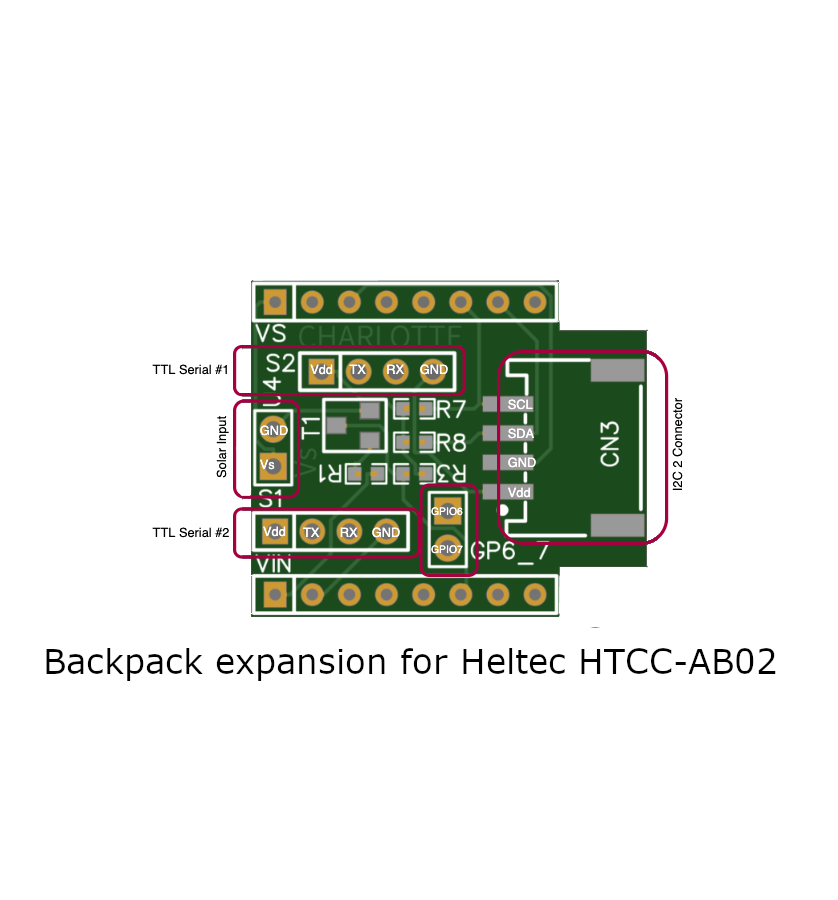
Can we get the option on the next version of boards to have a set of bridge pads to tie these to a GPIO?
My reason for this is to alter the behaviour and transmit interval based on the state of the power system.

While I am asking, a current sensor for the battery such as the INA219 would be a nice addition to the boards.

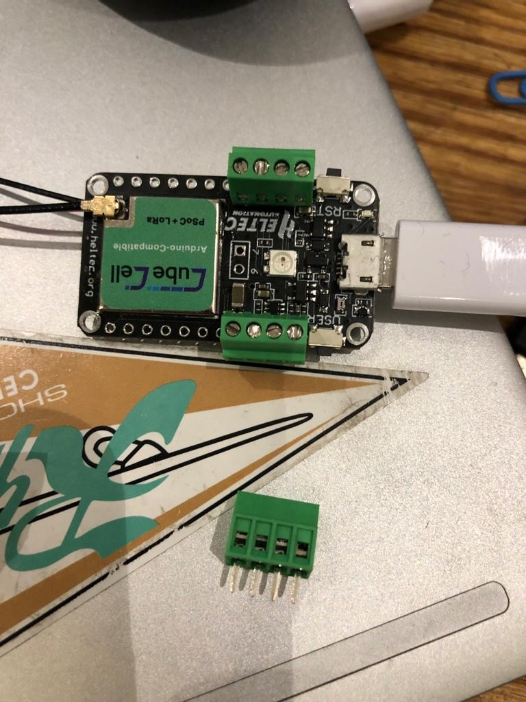
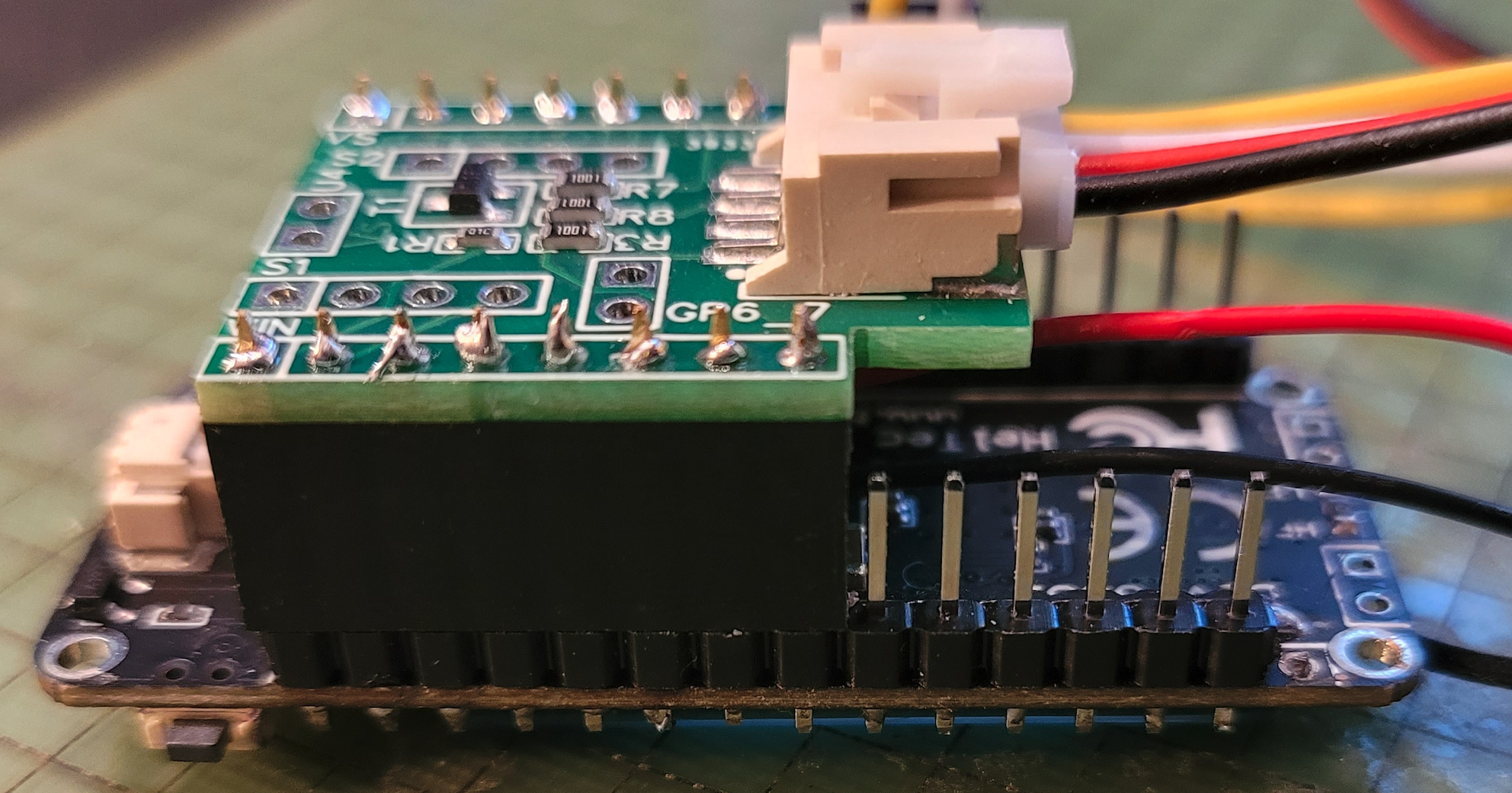
If anyone knows of a way to achieve these requests with the current boards it would be appreciated (I am using the Cubecell board and Dev-plus boards).

thanks,

-michael

you can use the battery level to determine if you are on power or battery…
see this example:

basically when an external power is plugged in the level will be higher than 4.1v based ob that you can run your logic…

cheers,
Jay

Unfortunately,

This does not add the information I need. My problem is two fold:

  1. My device has an internal temperature sensor. When charging, I am getting some self heating. I need a binary indicator that the device is charging (or not). There is a cute little red LED that comes on when charging. I need that signal for my program logic.
  2. I have tried the battery level and it is based on a calculation I am already performing

uint8_t BoardGetBatteryLevel()

{

            // 5.5 End-Device Status (DevStatusReq, DevStatusAns)

            // 0      The end-device is connected to an external power source.

            // 1..254 The battery level, 1 being at minimum and 254 being at maximum

            // 255    The end-device was not able to measure the battery level.

            const double maxBattery = 4.212;

            const double minBattery = 3.7;

            const double batVoltage = fmax(minBattery, fmin(maxBattery, getBatteryVoltage() / 1000.0));

            const uint8_t batlevel = BAT_LEVEL_EMPTY + ((batVoltage - minBattery) / (maxBattery - minBattery)) * (BAT_LEVEL_FULL - BAT_LEVEL_EMPTY);

            //printf("battery level (1-254): %u\n", batlevel);

            return batlevel;

}

Again, I need a binary indicator that the external power is present or not as this calculation does not produce consistent results due to battery age, ambient temperature, etc.

-michael

Hello,
try this:

uint16_t batteryVoltage = getBatteryVoltage();
Serial.print(batteryVoltage); //Basically when the power is plugged in this number will be above 4100mv since the lithium will require up to 4.2v to charge and will go below that when its not plugged in..

//for lora packet:
appData[0] = (uint8_t)(batteryVoltage >> 8);
appData[1] = (uint8_t)batteryVoltage;

Hi, The schematic for the AB01 board shows that the Vin pin is connected to the USB 5V. With a suitable voltage level shifter ( resistive divider, mosfet, or something similar) you should be able to detect whether USB power is present. There are blocking diode shown on the schematic which prevent the battery from back feeding voltage onto the USB port.

Don’t be tempted to connect Vin directly to a GPIO pin.

Yeah, I was thinking the same. Just did not want to add another PCB/component if there was some way to get the information. I am thinking of just moving the power and battery to an external PCB and add the needed logic outputs there. Maybe even an i2c interface like the laptop mfgs do. Better power diagnostics will be valuable improvements to the cubecell development boards since many of us are using them as-is in products.

thanks for the input,
-michael

The HTCC-AB01 has a TP4054 chip on board which is used for charging the battery, not only when USB is connected, but also when a Solar cell is connected and powering the board. The chip is located close to the RST button and the USB connector.
For my projects, I solder a wire to pin 1 of the TP4054 which is the inverted charging indicator (google the datasheet). That pin also drives the nice little led :slight_smile: 
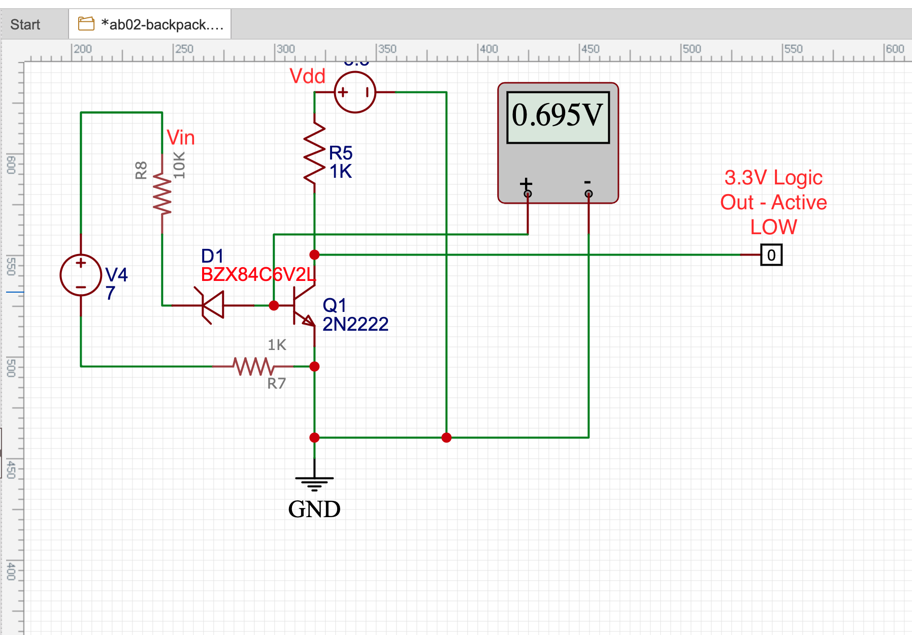
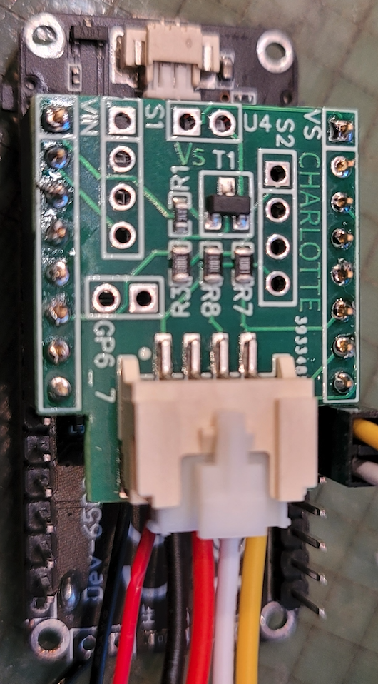
. It is low when the chip is actually charging the battery. but you must be careful - there seem to be different types of that chip on different production charges - some of these deliver 3.3V as high, some 5V. In the 5V case you need the voltage divider / MOSFET circuit before you connect the signal to a GPIO.

As an addition to my comment: I second the request that this signal is being made accessible - maybe as a solder pad like GPIO6 & GPIO7…

I agree, but the solder pad needs to be connected to a GPIO by default. I, like I suspect others are, am trying to use this as a module in a commercial product. Having to do a bunch of manual soldering is costly and quickly can surpass the costs of a custom PCB. Attached is a simple circuit to detect when Vin is connected to power. This could be built onto the PCB for little additional cost. I am currently running a small number of boards as a backpack for the AB02 to add this circuit and a SMD connector for the i2c bus. Now if I can just order the AB02s with the pin header pre-soldered, I will have eliminated 95% of my soldering during assembly.

-michael

Not able to “binary” detect between power mode and battery mode - is an operational gap on the board. I agree with Michael, that it is much more robust to build it with in the board design (vs add-on or error-prone soldering hacks).

While at it, if heltec wants to see the same level of success with this board (as nodemcu had with esp8266), offer the board with I/O pins pre-attached. It goes a long way to easily produce commercial products using this programmable board. Cubecell/LoRa has huge potential and it will be tapped if heltec can do these (minor) changes on their board design.

I really hope someone at heltec, watching this thread, can escalate to the right level and we see the change.

I actually disagree about the per-soldering of pin headers, for me it works great the way it is, as you can see below we use screw terminals, a much more robust and more professional system than the pin headers.


just my two cents
Cheers,
Jay

jayjay, I see your use case and point, but I stand by statement about soldering adding cost and complexity to lower quantity production products. In an ideal world, I would like to see the option for specifying a connector type for the headers when ordering in quantities of say 20 or 30+.

That makes it worth the effort by Heltec and you could choose from a few connector types (i.e. pin header, screw terminals and a JST type connector. I would also want to specify top or bottom mounting.

-michael

I am unable to find any guidelines that prohibit this post. If it is not allowed, please delete it.

So I finally broke down and designed a daughter board for the HTCC-AB02 module that adds the logic needed to detect when there is external power on Vin and provide a logic (LOW) signal to GPIO5. This allows my program to wake from sleep using an interrupt and take action when external power is lost or restored. I also added a “Grove” connector for SPI1 and header locations for other pins (serial0, serial1, Vs/GND and GPIO6/7.

I currently have it on tindie.com if anyone is interested. Shipping is set for USA destinations. Any others, please contact me and we can figure out the cheapest shipping method for your location.

If there is interest, I could create other “backpacks” for the other Heltec boards.

-michael

I bought a set of PicoBlade M-F Cable Kit to splice in one of INA2331 3-channel current sensor - one channel on the battery, one channel on the solar cell.

You just build a battery extension cable (2-pin MX1.25 M to F) and then cut the red wire and solder it to the V+/V- on a INA2331 (or ina219 if you don’t care about the solar).

The battery extension cables are handy anyway as when the CubeCell is inserted into another board its hard to unplug/plug the battery. Also handy to splice the compatible connector onto other batteries.

thanks for sharing, but the INA3221draws too much power draws about 350 µA according to the description, isn’t that a concern? or you have it powered by vin meaning it only measures when there is power supply plugged in? just trying to understand how you’re using it.

In my application 350ua is tolerable (and saved me more than 350ua in enabling other optimizations). I’m running off a 3000mah lipo and a couple solar cells.

But you can also sleep the device and measure intermittently if 350ua is intolerable.

ok thanks for the updates