Hello.
I am trying to run the ESP32_LoraWan example for CLASS A connection to the TNN service. I am in the US915 region. I have this problem: the node sucessfully joings TTN as shown in the picture below but the TNN console does not get the uplink message from the node… no data at all. I have tried everything but can’t find the fail. Below is the code.
Please, help!!!
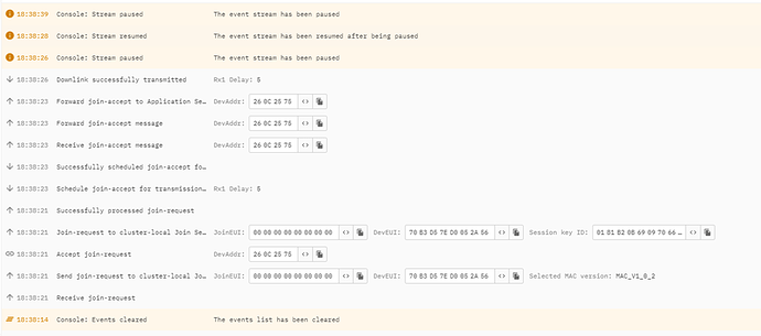
In this picture the TTN console shows the join request and accept but no data is get form the node.
Here you can see the node Arduino Ide serial console. Data is sent from the node but not received in the TTN.
15:54:53.634 -> ESP32ChipID=0C489F842178
15:54:53.728 -> ESP32 MCU init…
15:54:53.728 -> ESP32 MCU inited OK!
15:54:54.521 ->
15:54:54.521 -> DevEui=70B3D57ED0052A56
15:54:54.521 -> LoRaWAN US915 Class A start!
15:54:54.521 ->
15:54:54.942 -> joining…
15:54:54.988 -> TX on freq 903000000 Hz at DR 4
15:54:54.988 -> DIO0:TX Done
15:55:00.015 -> RX on freq 923300000 Hz at DR 13
15:55:00.015 -> DIO1:RX Timeout
15:55:01.009 -> RX on freq 923300000 Hz at DR 8
15:55:01.085 -> DIO1:RX Timeout
15:55:02.012 -> TX on freq 904900000 Hz at DR 0
15:55:02.431 -> DIO0:TX Done
15:55:07.421 -> RX on freq 926300000 Hz at DR 10
15:55:07.515 -> DIO0:RX Done
15:55:07.515 -> joined
15:55:08.999 -> In prepareTxFrame
15:55:08.999 -> unconfirmed uplink sending …
15:55:08.999 -> Deep Sleep until Next TxPacket:20548 ms
This is the code:
#include <ESP32_LoRaWAN.h>
#include “Arduino.h”
#define INT_PIN GPIO_NUM_0
/*license for Heltec ESP32 LoRaWan, quary your ChipID relevant license: http://resource.heltec.cn/search */
uint32_t license[4] = {0xA23D5041,0xC1CB6EFA,0x4A043DB2,0x743C23BE}; //chip_id = 24509F842178 device #10 chip_id = 0x5B4E68302
/* OTAA para*/
uint8_t DevEui[] = { 0x70, 0xB3, 0xD5, 0x7E, 0xD0, 0x05, 0x2A, 0x56 }; //uid=10 eui-70b3d57ed0052a56 MSB device #10
uint8_t AppEui[] = { 0x00, 0x00, 0x00, 0x00, 0x00, 0x00, 0x00, 0x00 };
uint8_t AppKey[] = { 0x3F, 0x09, 0x2C, 0xFE, 0x9B, 0x18, 0x38, 0x4B, 0x0C, 0x3F, 0x03, 0xE3, 0xAE, 0xB0, 0xCB, 0xB4 };
/* ABP para*/
uint8_t NwkSKey[] = { 0xC3, 0x5C, 0x49, 0x71, 0xBF, 0x55, 0x56, 0xDC, 0xC4, 0xF2, 0xFE, 0x6B, 0xBB, 0x37, 0x3F, 0x44 }; //eui-70b3d57ed0052a59
uint8_t AppSKey[] = { 0xB9, 0x4F, 0xCA, 0xA5, 0x45, 0x5C, 0xFC, 0x45, 0xF7, 0xFB, 0xB3, 0x31, 0xA4, 0x26, 0xEC, 0x6F };
//uint32_t DevAddr = ( uint32_t )0x260CFBB8; //for ABP
uint32_t DevAddr = ( uint32_t )0x260C5993; //6830;
/LoraWan channelsmask, default channels 0-7/
uint16_t userChannelsMask[6]={ 0xFF00,0x0000,0x0000,0x0000,0x0000,0x0000 }; //This is for TTN US915 SUB BAND 2
/LoraWan Class, Class A and Class C are supported/
DeviceClass_t loraWanClass = CLASS_A;
/the application data transmission duty cycle. value in [ms]./
uint32_t appTxDutyCycle = 20000;
/OTAA or ABP/
bool overTheAirActivation = true;
/ADR enable/
bool loraWanAdr = false;
/* Indicates if the node is sending confirmed or unconfirmed messages */
bool isTxConfirmed = false;
/* set LORAWAN_Net_Reserve ON, the node could save the network info to flash, when node reset not need to join again */
bool keepNet = false;
/* Application port */
uint8_t appPort = 2;
/*!
- Number of trials to transmit the frame, if the LoRaMAC layer did not
- receive an acknowledgment. The MAC performs a datarate adaptation,
- according to the LoRaWAN Specification V1.0.2, chapter 18.4, according
- to the following table:
- Transmission nb | Data Rate
- ----------------|-----------
- 1 (first) | DR
- 2 | DR
- 3 | max(DR-1,0)
- 4 | max(DR-1,0)
- 5 | max(DR-2,0)
- 6 | max(DR-2,0)
- 7 | max(DR-3,0)
- 8 | max(DR-3,0)
- Note, that if NbTrials is set to 1 or 2, the MAC will not decrease
- the datarate, in case the LoRaMAC layer did not receive an acknowledgment
*/
uint8_t confirmedNbTrials = 1;
/*LoraWan debug level, select in arduino IDE tools.
- None : print basic info.
- Freq : print Tx and Rx freq, DR info.
- Freq && DIO : print Tx and Rx freq, DR, DIO0 interrupt and DIO1 interrupt info.
- Freq && DIO && PW: print Tx and Rx freq, DR, DIO0 interrupt, DIO1 interrupt, MCU sleep and MCU wake info.
*/
uint8_t debugLevel = LoRaWAN_DEBUG_LEVEL;
/LoraWan region, select in arduino IDE tools/
LoRaMacRegion_t loraWanRegion = ACTIVE_REGION;
static void prepareTxFrame( uint8_t port )
{
Serial.println(“In prepareTxFrame”);
appDataSize = 4;
appData[0] = 0x00;
appData[1] = 0x01;
appData[2] = 0x02;
appData[3] = 0x03;
}
// Add your initialization code here
void setup()
{
if(mcuStarted==0)
{
LoRaWAN.displayMcuInit();
}
Serial.begin(115200);
while (!Serial);
uint64_t chipid=ESP.getEfuseMac();//The chip ID is essentially its MAC address(length: 6 bytes).
Serial.printf(“ESP32ChipID=%04X”,(uint16_t)(chipid>>32));//print High 2 bytes
Serial.printf("%08X\n",(uint32_t)chipid);//print Low 4bytes.
delay(100);
SPI.begin(SCK,MISO,MOSI,SS);
Mcu.init(SS,RST_LoRa,DIO0,DIO1,license);
delay(100);
deviceState = DEVICE_STATE_INIT;
}
// The loop function is called in an endless loop
void loop()
{
switch( deviceState )
{
case DEVICE_STATE_INIT:
{
#if(LORAWAN_DEVEUI_AUTO)
LoRaWAN.generateDeveuiByChipID();
#endif
LoRaWAN.init(loraWanClass,loraWanRegion);
break;
}
case DEVICE_STATE_JOIN:
{
LoRaWAN.displayJoining();
LoRaWAN.join();
break;
}
case DEVICE_STATE_SEND:
{
LoRaWAN.displaySending();
prepareTxFrame( appPort );
LoRaWAN.send(loraWanClass);
deviceState = DEVICE_STATE_CYCLE;
break;
}
case DEVICE_STATE_CYCLE:
{
// Schedule next packet transmission
txDutyCycleTime = appTxDutyCycle + randr( -APP_TX_DUTYCYCLE_RND, APP_TX_DUTYCYCLE_RND );
LoRaWAN.cycle(txDutyCycleTime);
deviceState = DEVICE_STATE_SLEEP;
  break;
}
case DEVICE_STATE_SLEEP:
{
  LoRaWAN.displayAck();
  esp_sleep_enable_ext0_wakeup(INT_PIN,0);
  LoRaWAN.sleep(loraWanClass,debugLevel);
  break;
}
default:
{
  deviceState = DEVICE_STATE_INIT;
  break;
}
}
}

