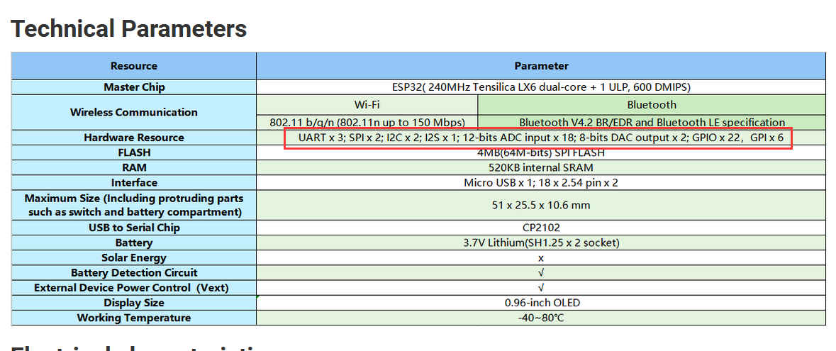
Hi, I have a ESP32 WiFi Kit 32, can someone clarify for me in total how many SPI and I2C channels the board has and which pins each corresponds to? If there is any limitation or caution in using them.
Thank you

Hi, I have a ESP32 WiFi Kit 32, can someone clarify for me in total how many SPI and I2C channels the board has and which pins each corresponds to? If there is any limitation or caution in using them.
Thank you
Thank you for your reply
My question has arisen from some problems I have encountered.
For my project I need to use an I2C bus (first for a RTC module) and an SPI bus (first for a SD card reader module) simultaneously and in shared mode.
I think the pins I can use are these, can you confirm this?
SPI:
MISO => 19
MOSI => 23
SCK => 18
CS => 5
I2C (shared with oled dispaly);
SDA: 4
SCL: 15
Do I have to do anything in particular to initialize the SPI channel?
Thank you
hi,
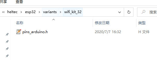
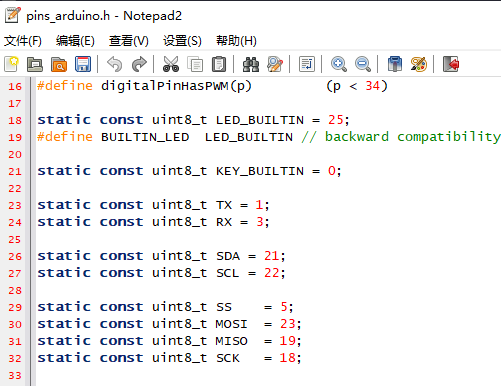
you can use the Pin redefinition please refer these picture:
Hi, regarding the SPI channel, I have tried to connect following SD reader board
compatible with a 3.3v power/bus with the suggested pins and using either a classic source with an SD library or passing to SD object costructor a SPICalsses pointer with a custom pin reference, but initialisation fails, do you have any suggestions?
Thank you
Hi, I suspect that SPI channel you shown me is not working or is not compatible for some reason with the Arduino 3.3v SPI sensors.
In fact, I did a little experiment using ESP32 WiFi as the SPI master, sending some packets to a “SparkFun Arduino Pro Mini 328 - 3.3V/8MHz” running as SPI slave and so far the communication didn’t work. To perform a further verification would you post me some examples to perform the test successfully?
Thank you
hi,
maybe you can refer this code. SD_card(SPI communication) for ESP32
https://github.com/HelTecAutomation/Heltec_ESP32/blob/master/examples/SD/SD_Time/SD_Time.ino
Hi have already tried the source.
The next step is to try to analyse the board’s SPI communication to understand what happens when the software libraries activate the flow and why the issue.
Thank you
Hi Jason, I have verified with a logic analyzer that the SPI bus works fine, the problem is due to the sd reader board that I managed to make it work and despite the specifications say that it can be powered at 3.3v and work with 3.3v logic in fact must be powered at 5v, I’m just worried that the board can get too high voltage and damage it.
I have the same problem with the I2c bus, I should connect a DS3231 on the pins you suggested, always power supply and 3.3v logic, but so far on the bus, with a scan, I see device addresses that are not connected except for its default address 0x57, I will continue to investigate.
Thank you
Regards
Hi, I have solved the issues.
Thank you
Regards