CubeCell LoRaWAN TX/RX process, power considerations

Hi, I am building a node that does sensor readouts on a cyclic scheme and then sends the results via LoRaWAN. In my lab I monitor the power consumption from the battery connector using a Power Profiler Kit II. For a typical cycle, I get the following:

You can see the power-on of Vext as a large (270 mA) but very short (300 µs) peak due to a capacitor loading, then the LoRa TX as a 120 mA / 68 ms peak shortly after (this is for SF7 and of course it gets longer with higher SFs). The typical current when the device is awake is about 10 mA. In sleep mode it draws about 10 µA.

I wonder if it is possible to tweak the process after the TX while retaining the RX window(s) as more than ⅔ of the energy is consumed there. Any ideas?

i’ve tinkered with this and was able to lower the power consumption to 6ma while up using the following code: basically i lowered the frequency to the minimum since my node doesn’t require any heavy calculation… work so far.

            CySysClkWriteSysclkDiv(CY_SYS_CLK_SYSCLK_DIV8);                                        //--> Provides a 24Mhz/DIV8 = 24/8 = 3 MHz clock. Lowest clock acceptable for SW Tx UART component.
            CySysFlashSetWaitCycles(CY_FLASH_CTL_WS_0_FREQ_MIN);                                   // CY_SYS_CLK_IMO_MIN_FREQ_MHZ / SYSCLK_DIVIDER / SYSCLK_DIVIDER / HFCLK_DIVIDER);
            CyDelayFreq(CY_SYS_CLK_IMO_MIN_FREQ_MHZ * HZ_IN_MHZ / SYSCLK_DIVIDER / HFCLK_DIVIDER); // 6u * HZ_IN_MHZ); // CY_SYS_CLK_IMO_MIN_FREQ_MHZ * HZ_IN_MHZ / SYSCLK_DIVIDER / SYSCLK_DIVIDER / HFCLK_DIVIDER); // to acheive 3Mhz must devide by 8

Cheers;
Jay

1 Like

Hi Jay,
thanks for the hint, this sounds interesting. Can you provide the complete code snippet as this is quite low-level? The constants SYSCLK_DIVIDER and HFCLK_DIVIDER are not defined in the headers and they seem to be essential for correct parametrization. Same goes for HZ_IN_MHZ but I guess this is simply a factor of 1000000.

So… I just tried with SYSCLK_DIVIDER = 8 and HFCLK_DIVIDER = 1. This seems to work in some way, as I can observe the computing speed going down by a factor of about 7.5. LoRaWAN seems to work. Reading sensors with I²C works with one of the sensors, however the other gives invalid readouts. Also the WS2812 LED shows incorrect colors, going to full power white (#FFFFFF) instead of e.g. a faint red (#010000) – the effect could be timing problems.

What is more relevant: The energy consumption for a sensor readout + LoRa Tx cycle is higher than it was before. The reason seems to be timing issues:

Original clock frequency for comparison (mind the axes):

The whole cycle is now almost 17 s, whereas before it was 8.5 s. The energy consumption is 80 mC with normal clock frequency and about 104 mC with reduced clock frequency. With frequency reduction the system does one phase of deep sleep in between, whereas before there were three such phases.

Hello @kater_s
Sorry about the missing parts:
you must include:

#include <cytypes.h>
#include <cyfitter.h>
#include <cydevice_trm.h>
#include <CyLib.h> 

#if (CY_IP_SRSSLT)
#define HFCLK_DIVIDER (2u)
#else
#define HFCLK_DIVIDER (1u)
#endif
//#define CLK_IMO_MHZ (24u)
#define SYSCLK_DIVIDER (2u)
#define HZ_IN_MHZ (1000000u)
uint32 clkSelectReg; // save the system clock in mhz

as for changing the frequency yes you must update other things that affect the correct timing, i remember reading about this when i was digging for the info… that’s where the CyDelayFreq does matches the right frequency with the correct timing… my settings might not be correct as this was done a while ago… so here are some of my notes from the project… please go through them and hopefully you will find the correct settings.

void setup()
{
    clkSelectReg = CY_SYS_CLK_SELECT_REG; // 24 Mhz keep track of the current settings
      // DEBUG_MSG(false, "\t\n Before clkSelectReg =%u", clkSelectReg);
      //  CySysClkWriteSysclkDiv(CY_SYS_CLK_SYSCLK_DIV1);
      //  DEBUG_MSG(false, "\t\n After clkSelectReg CY_SYS_CLK_SYSCLK_DIV1=%u", CY_SYS_CLK_SELECT_REG);
      //  CySysClkWriteSysclkDiv(CY_SYS_CLK_SYSCLK_DIV2);
      //  DEBUG_MSG(false, "\t\n After clkSelectReg CY_SYS_CLK_SYSCLK_DIV2=%u", CY_SYS_CLK_SELECT_REG);
      //  CySysClkWriteSysclkDiv(CY_SYS_CLK_SYSCLK_DIV4);
      //  DEBUG_MSG(false, "\t\n After clkSelectReg CY_SYS_CLK_SYSCLK_DIV4 <=12MHz=%u", CY_SYS_CLK_SELECT_REG);
      //  // Restore system clock configuration
      //  // CY_SYS_CLK_SELECT_REG = clkSelectReg;
      // Internal low power oscillator is stopped as it is not used in this project
      // CySysClkIloStop(); // This is actually already done in the clock settings in PSoC Creator, but this is how it is achieved in code.
      // Set the divider for ECO, ECO will be used as source when IMO is switched off to save power
      // CySysClkWriteEcoDiv(CY_SYS_CLK_ECO_DIV8); // --> Provides a 3 MHz clock. Lowest clock acceptable for SW Tx UART component.
      // change HF clock source from IMO to ECO, as IMO is not required and can be stopped to save power
      // CySysClkWriteHfclkDirect(CY_SYS_CLK_HFCLK_ECO);
      // stop IMO for reducing power consumption
      // CySysClkImoStop();
      // CySysFlashSetWaitCycles can optionally be called after lowering SYSCLK
      // clock frequency in order to improve the CPU performance.
      // CySysFlashSetWaitCycles(3); // Frequency in MHz
      // Update Delay frequency as clock frequency has changed
      // CyDelayFreq(3000000UL);
      // CySysClkWriteSysclkDiv(CY_SYS_CLK_SYSCLK_DIV8); //--> Provides a 24Mhz/DIV8 = 24/8 = 3 MHz clock. Lowest clock acceptable for SW Tx UART component.
      // DEBUG_MSG(false, "\t\n After clkSelectReg CY_SYS_CLK_SYSCLK_DIV8=%u\n", CY_SYS_CLK_SELECT_REG);
      // DEBUG_MSG(false, "CY_SYS_CLK_IMO_MIN_FREQ_MHZ / SYSCLK_DIVIDER / HFCLK_DIVIDER=%u\n", CY_SYS_CLK_IMO_MIN_FREQ_MHZ / SYSCLK_DIVIDER / HFCLK_DIVIDER);
      //  CySysFlashSetWaitCycles(CLK_IMO_MHZ / SYSCLK_DIVIDER / HFCLK_DIVIDER);
      // Adjustment for CyDelay function
      // CyDelayFreq(CLK_IMO_MHZ * HZ_IN_MHZ / SYSCLK_DIVIDER / HFCLK_DIVIDER);
      // CySysFlashSetWaitCycles(CY_SYS_CLK_IMO_MIN_FREQ_MHZ / SYSCLK_DIVIDER / SYSCLK_DIVIDER / HFCLK_DIVIDER);
      // Adjustment for CyDelay function
      // DEBUG_MSG(false, "CY_SYS_CLK_IMO_MIN_FREQ_MHZ * HZ_IN_MHZ / SYSCLK_DIVIDER / HFCLK_DIVIDER=%u\n", CY_SYS_CLK_IMO_MIN_FREQ_MHZ * HZ_IN_MHZ / SYSCLK_DIVIDER / HFCLK_DIVIDER);
      // CyDelayFreq(CY_SYS_CLK_IMO_MIN_FREQ_MHZ * HZ_IN_MHZ / SYSCLK_DIVIDER / SYSCLK_DIVIDER / HFCLK_DIVIDER); // to acheive 3Mhz must devide by 8
}

i remember i got it to work correctly where i can set the system to run on low power and restore it to full power if needed… but i can’t remember exactly what i did as i had to go through a lots of reading but the above should help you get there… if i have time i will trace my steps back and share them and if you get there before i do please share your findings.

here is one of the document i read to get there: https://community.infineon.com/gfawx74859/attachments/gfawx74859/psoc4/16113/1/cy_boot_v5_90_psoc4.pdf

cheers,
Jay

Hi again,
Basically here are the four different learnings i got out of it:

  1. when you decrease the frequency you should call CySysFlashSetWaitCycles after CySysClkWriteSysclkDiv
  2. when you try to increase the frequency back you must call CySysFlashSetWaitCycles before CySysClkWriteSysclkDiv or the system will halt.

so here are the different four scenarios i could get to work with the correct timing: please try them and let me know.

void setup(){
      // Enable ILO frequency
      CySysClkIloStart();
      //*************************Decrease the frequency to the minimum 6 Mhz************************************************************************************
      clkSelectReg = CY_SYS_CLK_SELECT_REG; // record the current system clock
      printf("\t\n Before clkSelectReg =%u", clkSelectReg);
      // note: when decreasing we call CySysClkWriteSysclkDiv before CySysFlashSetWaitCycles
      CySysClkWriteSysclkDiv(CY_SYS_CLK_SYSCLK_DIV8);
      // Set SYSCLK divider(increasing)
      CySysFlashSetWaitCycles(CY_FLASH_CTL_WS_0_FREQ_MAX); // from 0 - 16 mhz
      // Adjustment for CyDelay function
      CyDelayFreq(CY_SYS_CLK_IMO_MIN_FREQ_MHZ * HZ_IN_MHZ / SYSCLK_DIVIDER / HFCLK_DIVIDER);
      clkSelectReg = CY_SYS_CLK_SELECT_REG; // 24 Mhz
      printf("\t\n After clkSelectReg =%u", clkSelectReg);
      m = millis();
      CyDelay(4000);
      printf("\n Timing at 6Mhz:%d = 4040\n", millis() - m);
      //*************************************************************************************************************

      //************************* Increase it to 16 Mhz ************************************************************************************
      clkSelectReg = CY_SYS_CLK_SELECT_REG; // record the current system clock
      printf("\t\n Before clkSelectReg =%u", clkSelectReg);
      // note: when increasing we call CySysFlashSetWaitCycles before CySysClkWriteSysclkDiv
      CySysFlashSetWaitCycles(CY_FLASH_CTL_WS_1_FREQ_MAX); // 16 to 32 mhz
      // Set SYSCLK divider(increasing)
      CySysClkWriteSysclkDiv(CY_SYS_CLK_SYSCLK_DIV4);
      // Adjustment for CyDelay function
      CyDelayFreq(CY_SYS_CLK_IMO_MAX_FREQ_MHZ * HZ_IN_MHZ / SYSCLK_DIVIDER / HFCLK_DIVIDER);
      clkSelectReg = CY_SYS_CLK_SELECT_REG; // 24 Mhz
      printf("\t\n After clkSelectReg =%u", clkSelectReg);
      m = millis();
      delay(4000);
      printf("\n Timing at 16Mhz:%d = 4040\n", millis() - m);
      //*************************************************************************************************************

      //****************************** Increase it to 32 Mhz *******************************************************************************
      clkSelectReg = CY_SYS_CLK_SELECT_REG; // record the current system clock
      printf("\t\n Before clkSelectReg =%u", clkSelectReg);
      CySysFlashSetWaitCycles(CY_FLASH_CTL_WS_2_FREQ_MAX); // 32 to 48 mhz
      // Set SYSCLK divider(increasing)
      CySysClkWriteSysclkDiv(CY_SYS_CLK_SYSCLK_DIV2);
      // Adjustment for CyDelay function
      CyDelayFreq(CY_SYS_CLK_IMO_MAX_FREQ_MHZ * HZ_IN_MHZ / SYSCLK_DIVIDER);
      clkSelectReg = CY_SYS_CLK_SELECT_REG; // 24 Mhz
      printf("\t\n After clkSelectReg =%u", clkSelectReg);
      m = millis();
      delay(4000);
      printf("\n Timing at 32Mhz :%d = 4040\n", millis() - m);
      //*************************************************************************************************************

      //**************************** Increase it to 48 Mhz ***************************************************************
      clkSelectReg = CY_SYS_CLK_SELECT_REG; // record the current system clock
      printf("\t\n Before clkSelectReg =%u", clkSelectReg);
      // to increase the frequency one must set the FlashWaitCycle first
      CySysFlashSetWaitCycles(CY_FLASH_CTL_WS_2_FREQ_MAX); // 32 to 48 mhz
      // Set SYSCLK divider(increasing)
      CySysClkWriteSysclkDiv(CY_SYS_CLK_SYSCLK_DIV1); // which is 48Mhz
      // Adjustment for CyDelay function
      CyDelayFreq(CY_SYS_CLK_IMO_MAX_FREQ_MHZ * HZ_IN_MHZ); // or 0 which means default that is 48Mhz
      clkSelectReg = CY_SYS_CLK_SELECT_REG;                 // 24 Mhz
      printf("\t\n After clkSelectReg =%u", clkSelectReg);
      m = millis();
      delay(4000);
      printf("\n Timing at 48Mhz :%d = 4040\n", millis() - m);
      //*************************************************************************************************************
}

Hi Jay,

thank you for your advice. I now use a utility function like

void switch_freq(bool throttle = true)
{
#if (CY_IP_SRSSLT)
#define HFCLK_DIVIDER (2u)
#else
#define HFCLK_DIVIDER (1u)
#endif
  //#define CLK_IMO_MHz (24u)
#define SYSCLK_DIVIDER (2u)
#define HZ_IN_MHZ (1000000u)
  uint32 clkSelectReg; // save the system clock in MHz
  if (throttle) {
    CySysClkIloStart(); // enable ILO frequency
    // decrease system clock to the minimum of 6 MHz
    clkSelectReg = CY_SYS_CLK_SELECT_REG; // record the current system clock
    Serial.println((String)"Before: clkSelectReg = " + clkSelectReg);
    // note: when decreasing we call CySysClkWriteSysclkDiv before CySysFlashSetWaitCycles
    CySysClkWriteSysclkDiv(CY_SYS_CLK_SYSCLK_DIV8);
    // Set SYSCLK divider(increasing)
    CySysFlashSetWaitCycles(CY_FLASH_CTL_WS_0_FREQ_MAX); // from 0 - 16 mhz
    // Adjustment for CyDelay function
    CyDelayFreq(CY_SYS_CLK_IMO_MIN_FREQ_MHZ * HZ_IN_MHZ / SYSCLK_DIVIDER / HFCLK_DIVIDER);
    clkSelectReg = CY_SYS_CLK_SELECT_REG; // 24 MHz
    Serial.println((String)"After: clkSelectReg = " + clkSelectReg);
  } else {
    // increase system clock to standard value of 48 MHz
    clkSelectReg = CY_SYS_CLK_SELECT_REG; // record the current system clock
    Serial.println((String)"Before: clkSelectReg = " + clkSelectReg);
    // to increase the frequency one must set the FlashWaitCycle first
    CySysFlashSetWaitCycles(CY_FLASH_CTL_WS_2_FREQ_MAX); // 32 to 48 mhz
    // Set SYSCLK divider(increasing)
    CySysClkWriteSysclkDiv(CY_SYS_CLK_SYSCLK_DIV1); // which is 48MHz
    // Adjustment for CyDelay function
    CyDelayFreq(CY_SYS_CLK_IMO_MAX_FREQ_MHZ * HZ_IN_MHZ); // or 0 which means default that is 48MHz
    clkSelectReg = CY_SYS_CLK_SELECT_REG;                 // 24 MHz
    CySysClkIloStop();  // disable ILO frequency
    Serial.println((String)"After: clkSelectReg = " + clkSelectReg);
  }
  Serial.println("clock frequency switched to " + String(throttle ? "low" : "high"));
}

I added the CySysClkIloStop() call when switching back to fast mode. Is that correct?

The standard delay() calls are working properly, calculations seem to run at about 12% of the normal speed, which is in accordance with the frequency being switched from 48 to 6 MHz.

Findings:

  1. The power consumption in normal (non-sleep) mode with external power (Vext) turned off goes from about 11 mA to about 6 mA, which is fine.

  2. Due to a different timing as described in my previous post, the LoRaWAN Tx cycle still needs more energy in slow mode (about 100 mC in comparison to 80 mC in fast mode), so slowing down the frequency does not pay off in my application case. Any ideas? Maybe I should try the intermediate clock rates (16/32 MHz). Or maybe I still got something wrong in the system calls.

  3. The WS2812 LED does not work in slow mode, it seems to be a problem in the ASR_NeoPixelShow() function of the CubeCell_NeoPixel module, which is unfortunately not given in source (it’s part of the CubeCellLib.a file). If I really need LED signals I temporarily switch back to fast mode as a viable workaround.

Hello @kater_s
in my application the system wakes up from interrupt to take a pulse and goes back to sleep which happens around 5 times a minute so bringing that consumption down from 10ma to 6ma paysoff for me, even though the processing time is longer, the overall savings in power consumption is almost 50%.

CPU running in normal mode:

after running the code below:

// Enable ILO frequency
  CySysClkIloStart();
  //*************************Decrease the frequency to the minimum 6 Mhz************************************************************************************
  // note: when decreasing we call CySysClkWriteSysclkDiv before CySysFlashSetWaitCycles
  CySysClkWriteSysclkDiv(CY_SYS_CLK_SYSCLK_DIV8);
  // Set SYSCLK divider(decreasing)
  CySysFlashSetWaitCycles(CY_FLASH_CTL_WS_0_FREQ_MAX); // from 0 - 16 mhz
  // Adjustment for CyDelay function
  CyDelayFreq(CY_SYS_CLK_IMO_MIN_FREQ_MHZ * HZ_IN_MHZ / SYSCLK_DIVIDER / HFCLK_DIVIDER);
  clkSelectReg = CY_SYS_CLK_SELECT_REG; // 24 Mhz
  printf("\t\n After clkSelectReg =%u", clkSelectReg);
//*************************************************************************************************************

the results are:

as to point 2:
honesty i’m not sure as i never actually paid attention to the energy required before this, as my focus was always on the power consumption maybe you can share more details as to how this affects the battery life (would be grateful to understand that mc and uc ) as i couldn’t find any info on that…
as to point 3:
yes it’s a timing issue and more involved than you think according to this article. Section “Can I control NeoPixels using (Board X)?”


also read the last section to understand how it works.
and finally you can try to get the code for PSOC4 from here and mess with it.
but first read this : https://www.hackster.io/juanespj/psoc-neopixel-easy-lightweight-library-ac6884
code: https://github.com/juanespj/PSoC_Neopixel/tree/main/NeoPixel/NeoPixel.cydsn/Generated_Source/PSoC4

if you don’t want to mess with any of the complexity of it, you can always switch back to 48mhz when trying to show the LED.

if you do find the solution please let us know.

Hi Jay,

Regarding the WS2812 LED: I know that timing is quite critical here, thank you for the pointer to the Cypress code. For my application it is sufficient to just use the workaround with switching to full-speed 48 MHz clock as the LED is used only when starting up.

Understanding the µC and mC is quite easy. “C” means Coulomb, which is a unit of electric charge. 1 Coulomb is the charge that a current of 1 Ampere switched on over a period of 1 second delivers, so basically it means current * time. You can think of this in terms of “amount of electrons”, with 1 Coulomb being 6241509074460762607 electrons (= 6.24 * 10^18 = 6.24e18 electrons).

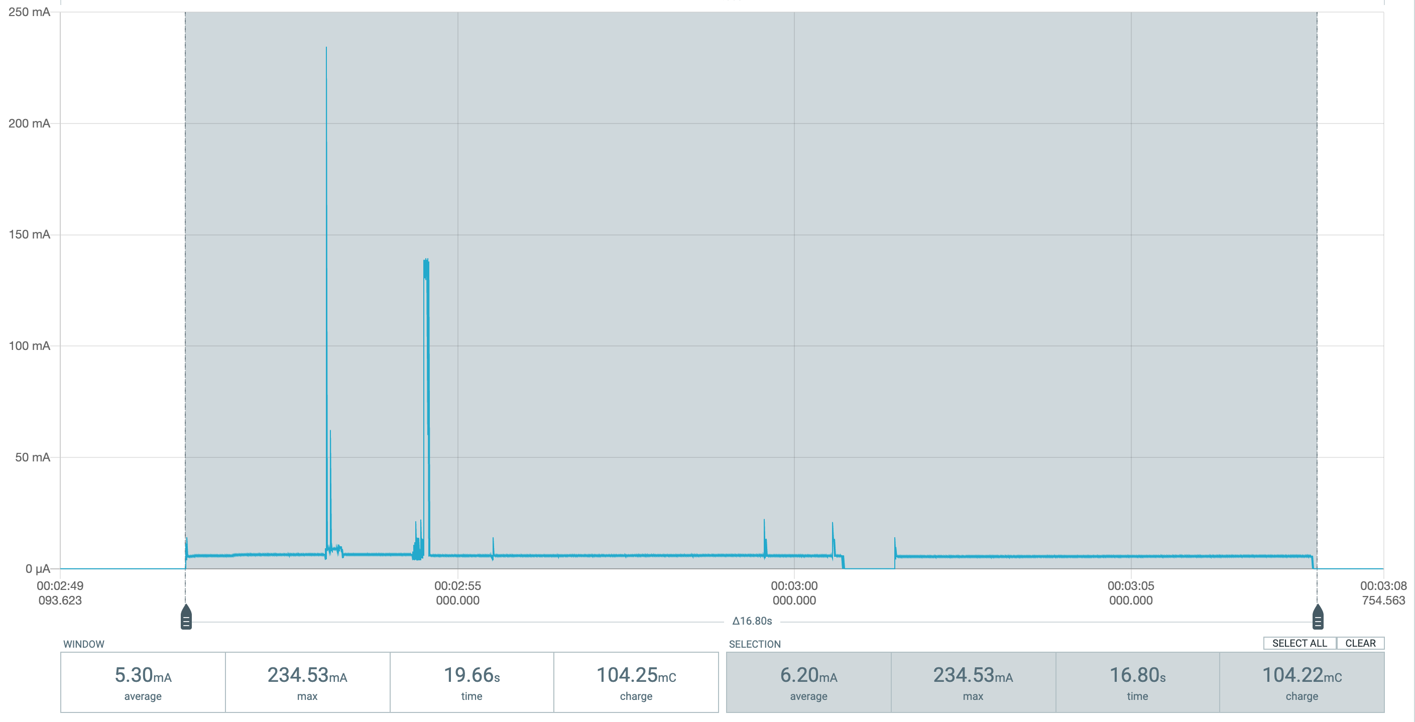
With changing current this evolves to the integral of current over time, so it’s the area under the current curve in the diagrams (or, the averaged current multiplied by the time). If, as in your first example, a processing cycle needs 10 mA over 40 ms, this is an energy of 0.010 A * 0.040 s = 0.0004 C = 400 µC. This matches the values shown in the grey box in the diagram because the current is mainly constantly at 10 mA.

The energy specified for a battery (rechargeable or not) is usually given in mAh, which is the same dimension but in a different unit than Coulombs. 1 mAh = 1 mA * 1 h = 0.001 A * 3600 s = 3,6 C. So if you have a off-the-shelf LiSOCl₂ battery with 2600 mAh, this would be 9.36 C. Simply calculated, this would be sufficient for 2,340,000 cycles, but of course this ignores other factors such as self discharge and aging of the battery.

We’re talking of constant voltage here. If we take the voltage into consideration, we would have Watts instead of Amperes (1 W = 1 V * 1 A). Together with the time we get Wattseconds, or Joules
(1 Ws = 1 V * 1 As = 1 V * 1 C = 1 J) as a unit of energy. So the 2600 mAh battery which has 3.6 Volts holds an energy of 9,36 Wh = 33,696 Ws ≈ 33.7 kJ.
But as long as the voltage is constant, electric charge and energy are proportional.

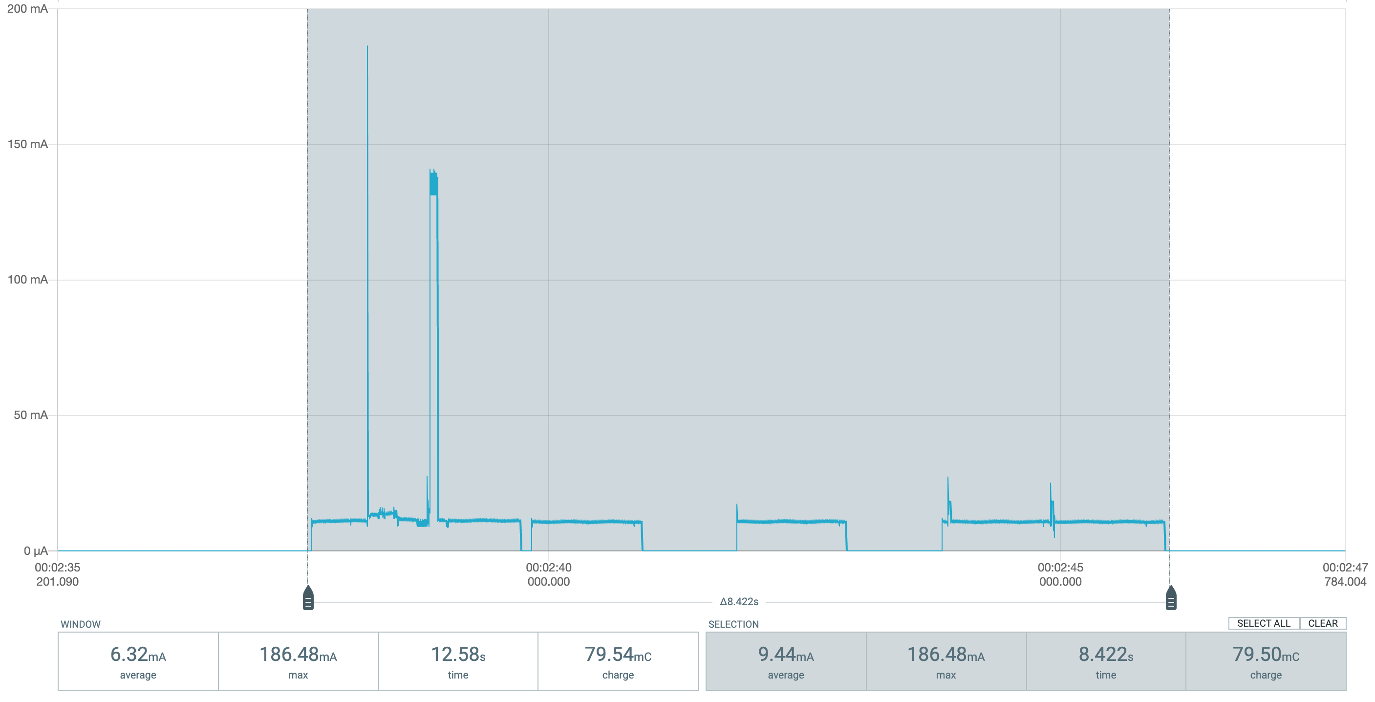
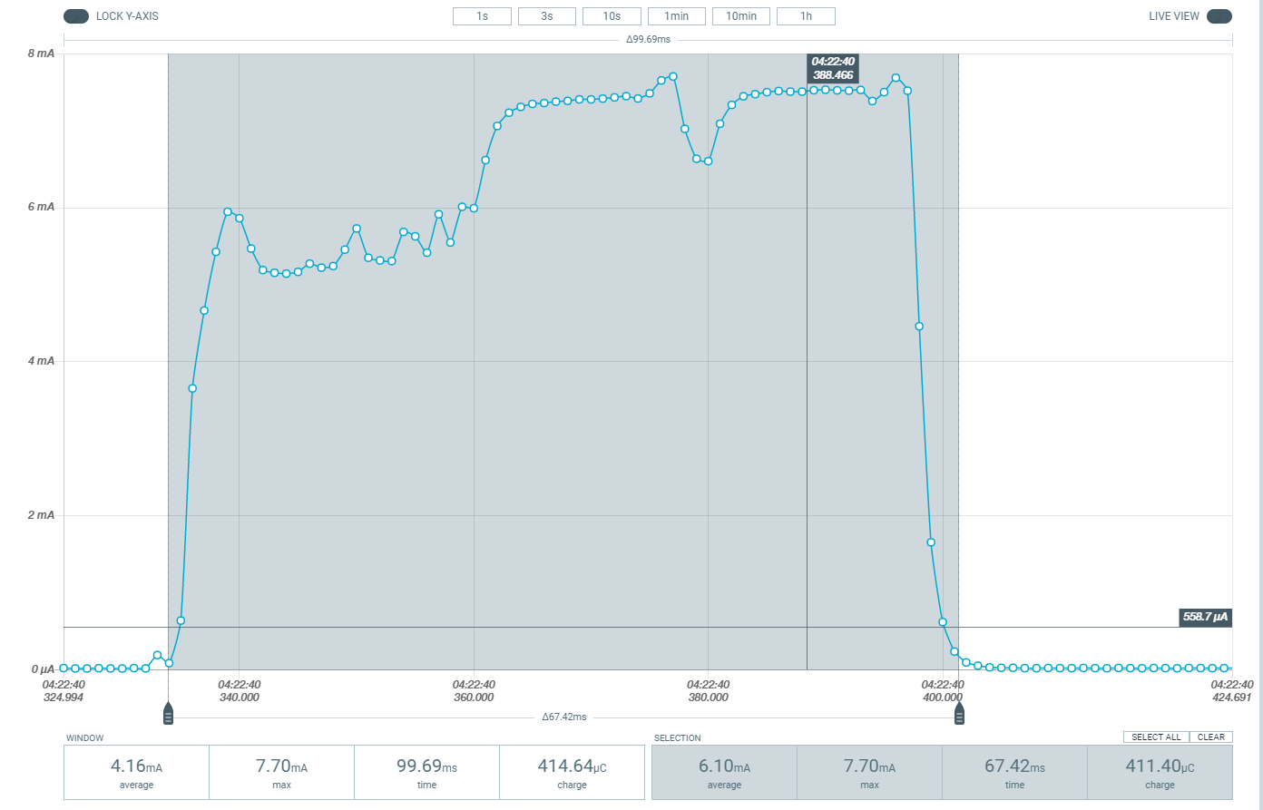
When comparing the two diagrams you sent, the second one with reduced clock frequency shows an average current of 6.1 mA over the course of a cycle which needs 67.42 ms, resulting in a charge of 6.1e-3 A x 67.42e-3 s = 411.4 µC as shown in the grey box. This is actually more than the full-speed version’s 389 µC, so theoretically reducing power has no positive effect here.
This could be a consequence of the fact that power consumption in CMOS circuits occurs when MOSFETs (transistors) are switching state, which is (kind of) proportional to the number of computation steps being executed. So there is little difference in energy consumption when the same calculation is carried out quickly with high power or slowly with low power. It only gets interesting when secondary effects have to be taken into consideration, e.g. operating system tasks or phases when the system is waiting for something external and CPU usage is less than 100% (wait cycles, elapsed time, sensor input, etc.).

In my case, I am wondering if reducing the clock speed, and therefore current consumption, could give a positive effect as I do not execute relevant amounts of calculation but mainly have to wait for the sensors to come up and do their measurements. Reducing current here could be worthwhile. But on the other hand, if the operating system (i.e. runtime environment and system libraries) behaves completely different depending on the clock setting, this may be counterproductive. I am referring to the lacking sleep phases during the LoRaWAN Tx/Rx phase here.

1 Like

I tried a bit more with the different clock frequency reduction settings. The best result is with 16 MHz, not 6 MHz. Going from full-speed 48 MHz over 32 MHz to 16 MHz constantly reduces power consumption per cycle (80 → 65 → 61 mC), but switching to 6 MHz increases it (104 mC!), presumably due to the very different sleep behaviour.

If there are no suitable settings below 16 MHz, I’ll stick with that.

1 Like

Thank you so much for the explanation, now it all makes sense.

Hi @kater_s,
so going directly from 48Mhz to 16Mhz has different results than going from 48Mhz to 32 to 16?

can you share your final code please…

EDIT: i’ve been meaning to ask this:
i have my cube cell connected to a hall effect cable coming out of a water meter, the cable is about two meter long, i’m using interrutps to read the pulse when the switch is closed. one end is connected to GPIO5 and the other to GND and i attach the pin as follow:

  pinMode(PULSE_PIN, INPUT_PULLUP);
  attachInterrupt(PULSE_PIN, ISR_Pulse, RISING);

now when the switch is engaged and stays engaged for a while (Meter turning real slow) the power consumption is high in this state…

so i figured maybe i should keep the pin floating pinMode(PULSE_PIN, INPUT); and use an external pull up resistor at a high value so little current is passing through… but i couldn’t come up with the correct value, i tried 1M ohm and that brought the consumption from 10ma to 30ua while in that state but is that the right value to use or is it too high. also since the cable is two meter long sometimes it acts as an antenna and creates a fake pulse so adding a 10k in series seems to help but not by much… any idea on how to tackle this with the right setup and Resistor values?

also do you know the impedance of the pins on these boards i couldn’t find that info?

Thanks for the update and testing.
Jay.

Sorry, I did not get a notice on your reply.

No, perhaps this misconception is due to my wording. What I wanted to say: energy consumption is highest with 48 MHz, lower with 32 MHz and even lower with 16 MHz. But with 6 MHz it is higher even than with 48 MHz. This is not dependent on the order in which these modes are activated, actually I tested each one by compiling and uploading. Maybe it has to do with the sleep timing.

So @16 MHz I get the lowest consumption for a measurement+tx cycle.

Have a look here:

// switch system frequency to lowest possible setting in order to save energy

void switch_freq(bool throttle = true)
{
#if (CY_IP_SRSSLT)
#define HFCLK_DIVIDER (2u)
#else
#define HFCLK_DIVIDER (1u)
#endif
#define SYSCLK_DIVIDER (2u)
#define HZ_IN_MHZ (1000000u)
  uint32 clkSelectReg; // save the system clock in MHz
  if (throttle) {
    CySysClkIloStart(); // enable ILO frequency
    clkSelectReg = CY_SYS_CLK_SELECT_REG; // record the current system clock
    LOG3ln((String)"Before: clkSelectReg = " + clkSelectReg);
    // note: when decreasing we call CySysClkWriteSysclkDiv before CySysFlashSetWaitCycles
#if 0
    // decrease system clock to the minimum of 6 MHz
    CySysClkWriteSysclkDiv(CY_SYS_CLK_SYSCLK_DIV8);
    // Set SYSCLK divider(increasing)
    CySysFlashSetWaitCycles(CY_FLASH_CTL_WS_0_FREQ_MAX); // from 0 - 16 mhz
    // Adjustment for CyDelay function
    CyDelayFreq(CY_SYS_CLK_IMO_MIN_FREQ_MHZ * HZ_IN_MHZ / SYSCLK_DIVIDER / HFCLK_DIVIDER);
#elif 1
    // decrease system clock to 16 MHz
    CySysClkWriteSysclkDiv(CY_SYS_CLK_SYSCLK_DIV4);
    // Set SYSCLK divider(increasing)
    CySysFlashSetWaitCycles(CY_FLASH_CTL_WS_1_FREQ_MAX); // from 0 - 16 mhz
    // Adjustment for CyDelay function
    CyDelayFreq(CY_SYS_CLK_IMO_MAX_FREQ_MHZ * HZ_IN_MHZ / SYSCLK_DIVIDER / HFCLK_DIVIDER);
#else
    // decrease system clock to 32 MHz
    CySysClkWriteSysclkDiv(CY_SYS_CLK_SYSCLK_DIV2);
    // Set SYSCLK divider(increasing)
    CySysFlashSetWaitCycles(CY_FLASH_CTL_WS_2_FREQ_MAX); // from 0 - 16 mhz
    // Adjustment for CyDelay function
    CyDelayFreq(CY_SYS_CLK_IMO_MAX_FREQ_MHZ * HZ_IN_MHZ / SYSCLK_DIVIDER);
#endif
    clkSelectReg = CY_SYS_CLK_SELECT_REG; // 24 MHz
    LOG3ln((String)"After: clkSelectReg = " + clkSelectReg);
  } else {
    // increase system clock to standard value of 48 MHz
    clkSelectReg = CY_SYS_CLK_SELECT_REG; // record the current system clock
    LOG3ln((String)"Before: clkSelectReg = " + clkSelectReg);
    // to increase the frequency one must set the FlashWaitCycle first
    CySysFlashSetWaitCycles(CY_FLASH_CTL_WS_2_FREQ_MAX); // 32 to 48 mhz
    // Set SYSCLK divider(increasing)
    CySysClkWriteSysclkDiv(CY_SYS_CLK_SYSCLK_DIV1); // which is 48MHz
    // Adjustment for CyDelay function
    CyDelayFreq(CY_SYS_CLK_IMO_MAX_FREQ_MHZ * HZ_IN_MHZ); // or 0 which means default that is 48MHz
    clkSelectReg = CY_SYS_CLK_SELECT_REG;                 // 24 MHz
    CySysClkIloStop();  // disable ILO frequency
    LOG3ln((String)"After: clkSelectReg = " + clkSelectReg);
  }
  LOG0ln("clock frequency switched to " + String(throttle ? "low" : "high"));
}

Note the #if 0 … #elif 1 … #else … #endif cascade that is used to test the different reduced clock settings. I finally sticked with 16 MHz as shown here.

No guarantee that this is the correct way to achieve the task, as there is no sufficient documentation about it. But for me it seems to work, apart from the strange fact that 16 MHz is the optimum, not 6 MHz.