
Hola a todos.
Currently I have been using the Cubecell HTCC-AB01, which I am using for a project where I need to transmit data from sensors, the reason why I chose the cubecell was its low consumption, and I have the power profiler kit 2 for which I can Make sure if it consumes little or not, I have been carrying out the corresponding consumption tests using the following sample code:
#include “LoRaWan_APP.h”
#include “Arduino.h”
/* OTAA para*/
uint8_t devEui[] = { };
uint8_t appEui[] = { };
uint8_t appKey[] = {};
/* ABP para*/
uint8_t nwkSKey[] = { 0x15, 0xb1, 0xd0, 0xef, 0xa4, 0x63, 0xdf, 0xbe, 0x3d, 0x11, 0x18, 0x1e, 0x1e, 0xc7, 0xda,0x85 };
uint8_t appSKey[] = { 0xd7, 0x2c, 0x78, 0x75, 0x8c, 0xdc, 0xca, 0xbf, 0x55, 0xee, 0x4a, 0x77, 0x8d, 0x16, 0xef,0x67 };
uint32_t devAddr = ( uint32_t )0x007e6ae1;
/LoraWan channelsmask, default channels 0-7/
uint16_t userChannelsMask[6]={ 0x0000,0x00FF,0x0000,0x0000,0x0000,0x0000 }; //FSB3
//uint16_t userChannelsMask[6]={ 0xFF00,0x00FF,0x0000,0x0000,0x0000,0x0000 }; //FSB2
/LoraWan region, select in arduino IDE tools/
LoRaMacRegion_t loraWanRegion = ACTIVE_REGION;
/LoraWan Class, Class A and Class C are supported/
DeviceClass_t loraWanClass = LORAWAN_CLASS;
/the application data transmission duty cycle. value in [ms]./
uint32_t appTxDutyCycle = 1200000;
/OTAA or ABP/
bool overTheAirActivation = LORAWAN_NETMODE;
/ADR enable/
bool loraWanAdr = LORAWAN_ADR;
/* set LORAWAN_Net_Reserve ON, the node could save the network info to flash, when node reset not need to join again */
bool keepNet = LORAWAN_NET_RESERVE;
/* Indicates if the node is sending confirmed or unconfirmed messages */
bool isTxConfirmed = LORAWAN_UPLINKMODE;
/* Application port */
uint8_t appPort = 6;
uint8_t confirmedNbTrials = 4;
/* Prepares the payload of the frame */
static void prepareTxFrame( uint8_t port )
{
appDataSize = 4;
appData[0] = 0x00;
appData[1] = 0x01;
appData[2] = 0x02;
appData[3] = 0x03;
}
//downlink data handle function example
/*void downLinkDataHandle(McpsIndication_t *mcpsIndication)
{
Serial.printf("+REV DATA:RXSIZE %d,PORT %d\r\n",mcpsIndication->BufferSize,mcpsIndication->Port);
Serial.print("+REV DATA:");
for(uint8_t i=0;iBufferSize;i++)
{
Serial.printf("%02X",mcpsIndication->Buffer[i]);
}
Serial.println();
}
*/
void setup() {
Serial.begin(115200);
#if(AT_SUPPORT)
enableAt();
#endif
deviceState = DEVICE_STATE_INIT;
LoRaWAN.ifskipjoin();
}
void loop()
{
switch( deviceState )
{
case DEVICE_STATE_INIT:
{
#if(LORAWAN_DEVEUI_AUTO)
LoRaWAN.generateDeveuiByChipID();
#endif
#if(AT_SUPPORT)
getDevParam();
#endif
printDevParam();
LoRaWAN.init(loraWanClass,loraWanRegion);
deviceState = DEVICE_STATE_JOIN;
break;
}
case DEVICE_STATE_JOIN:
{
LoRaWAN.join();
break;
}
case DEVICE_STATE_SEND:
{
prepareTxFrame( appPort );
LoRaWAN.send();
deviceState = DEVICE_STATE_CYCLE;
break;
}
case DEVICE_STATE_CYCLE:
{
// Schedule next packet transmission
txDutyCycleTime = appTxDutyCycle + randr( 0, APP_TX_DUTYCYCLE_RND );
LoRaWAN.cycle(txDutyCycleTime);
deviceState = DEVICE_STATE_SLEEP;
break;
}
case DEVICE_STATE_SLEEP:
{
LoRaWAN.sleep();
break;
}
default:
{
deviceState = DEVICE_STATE_INIT;
break;
}
}
}
And here is the interesting thing, I have 4 rechargeable batteries of 2800mAh of 1.2V each, of which I feed the cubecell by the VIN pin indicated in the datasheet when performing the consumption tests I obtain the following result:
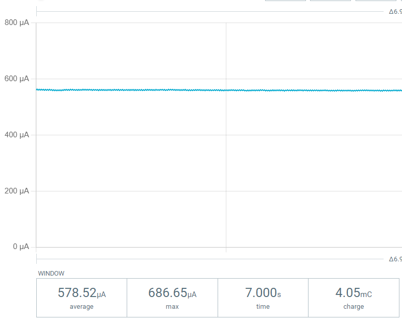
Now the datasheet mentions that when feeding through that pin, the consumption should be around 10uA. Now, after long hours researching and testing, it occurred to me to connect it to the pin where the solar panel should be connected, which would be VS and GND. And to surprise:
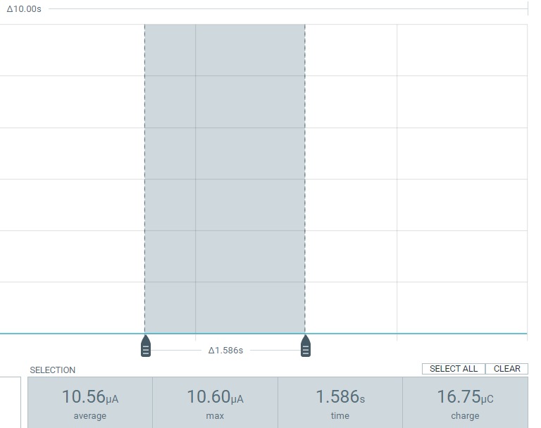
The consumption indicates only 10.56uA which is perfect, but when I feed it for that PIn, the cubecell is unable to send a payload to TTN. I am aware that I could try powering it through the 3.3V pin or with a 3.7V lithium battery but I want to use the batteries that I mentioned above. I do not understand what is happening, why there is such a difference in consumption.