CubeCell and Second Serial Port

I have an MLX IR camera and looking at ways to set up a trigger warning should one or more pixels report a temperature level above what has been set.
Using I2C seems not to be an option as the array sent back apparently requires about 20k of ram. The sensor however has its own processor that will send back the data via a setial link.
My thoughts were to read the fist line, do the compare, read the next etc…

However it seems the Software Serial libraries dont seem to work on the CubeCell and by the looks the existing serial is tied to the USB.

Has anyone seen any software serial lib’s that will work with the CubeCell.

There is no software serial library for the CubeCell devices based on the ASR6501

So there is no way to run a second serial port on the CubeCell for communicating to other devices?

I am not aware of it

Yes, you can add SC16IS740 (IC) or buy a breakout board (https://www.sparkfun.com/products/retired/9981).

Great find
Just bought one and will test

I’have made a PCB with one SC16IS740 to have SDI-12 to read sensor for agriculture (like 5TE from Meter Group - https://www.metergroup.com/environment/articles/meter-legacy-soil-moisture-sensors/#5te).
For simple UART you can try this library (https://github.com/rickkas7/SC16IS740RK).

i will give the library a try when my breakoutboard arrive

1 Like

Greetings from France! I successfully integrate temperature/hygrometry with the combo nodered-influxdb-grafana with both HTCC-AB01 (1xADC for battery readings) and HTCC-AB02 (3xADC). I’m really happy with the Heltec team works.

My goal is to make my own pcb with Heltec modules HTCC-AM02 (and to solder myself :slight_smile: ). I just want to integrate this famous irrometer Watermark SS200 in my circuit.
My application only need only one watermark probe/battery reading/I2C for my temp/hygro sensor.
@avalente I read your publication and loved that but I’m struggling to make the right choice for the watermark circuit.

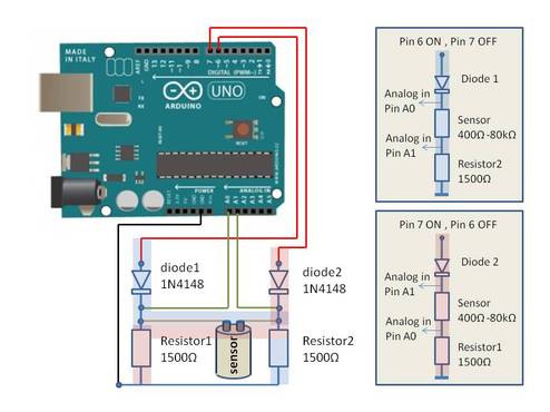
I want to take readings frome the watermark but without the multiplexers or LMC555 like Fasal and you propose on his github https://github.com/Fasal-Tech/irrometer555-withMux
Can you guys have a light component consumming solution for the watermark integration without multiplexing? Which pins shloud I use and what reading methods.
Is the schematic from Watermark Schematic page is a good start or do I have to complexify with diodes and caps like Fasal propose?

I have watermark probes to to both prototyping and code testing right now with the HTCC-AB02 dev board.
Next step is to design all the circuitery around the HTCC-AM02 module but some components seems to be hard to find in JLCPCB (i.e U1 CE6260). I thinking to just replicate the Arduino reference design for HTCC-AM02.
Let me know if the community can help me with this design. Thanks in advance.
Alex

Hi @AlexFR, the Watermark sensor is a resistive sensor. As it is to be in contact with water and salts, its reading requires some care (electrolysis). In the Fasal circuit, the excitation of the sensor is alternated by the 555 and the output is in frequency. In my case, the ‘alternation’ is done through GPIO0 and GPIO5 (identical to what is on the website in Figure 1 with Pseudo-AC). As I used HTCC-AB01 which only has one ADC I had to use an external ADC (18-bit I2C MCP3421) in the case of HTCC-AB02 which has 3 ch. you can use two to read the Watermark (remember that reading has to be differential). No multiplexer is required for only one sensor.

1 Like

Hello @avalente, as you oriented me with the reference schematic I’m stil struggling to put in place the pseudo ac.
To be clear, I should substitute A0 with ADC2 and A1 with ADC3 for differential readings (Ok with my HTCC-AB02) but the “PWM” induce me in error. ( I should replace this with two GPIO’s alternating on&off like the GPIO5&0 you use ?). When I compare with your schematics Vext induce me in error.


Could you help me with a simple schematic for my case (pseudo ac using one watermak probe and two ADC’s ?) In that case my circuit will be simmilar to this arduino one (minus diodes) ? 4533105 
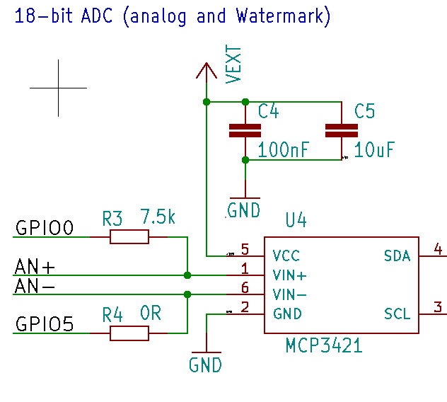
. Thank again for your response.

Hi @AlexFR, VEXT is only the HTCC-AB02 3.3V power (you can switch on/off this power). The idea is the same of the one with Arduino but without diodes (these are only for short-circuit protection). First place GPIO0 high and GPIO5 low and measure ADC2-ADC3 and then reverse (GPIO0 low and GPIO5 high) and read ADC3-ADC2. Take some measurements (less than 50ms) and then place GPIO0 and GPIO5 as input (Hi-Z).