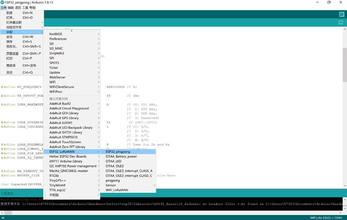
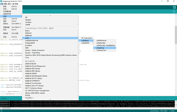
I have a cube cell board and a Heltec esp32 v2 that I have been trying to talk to each other through lora. my problems are vast. my biggest problem is that none of the lora libraries that i have tried will work with both boards. I’ve tried the examples that come with the esp 32 and a cut up version of the ping pong sketch but cant get them to communicate. they are both supposed to be 868, and ive changed both sketches to reflect that but still no luck. any ideas would be appreciated.
Cube cell and esp32 lora problems
Do you have spectrum analyzer equipment around you? Maybe you should check the RF performance of these two boards.
Use RadioLib.h library for ESP32 V2 and pingpong.ino for CubeCell.
In RadioLib change parameter setSyncWord(0x14)
Rest must be the same.
Thats all, works perfect.
link to library: https://github.com/jgromes/RadioLib
Bonmis
I have described how I have ESP32 V1 (but should be essentially the same as V2), Wireless Stick Lite and CubeCell modules communicating via LoRa here, per my response to a similar question here (links to all scripts included). I’m not claiming that I’m doing things the best way, but it all works and should at least provide a starting point for anyone trying to validate their hardware configuration.
I wrote two examples, how it can make sense to you:
The example function is read CubeCell’s battery voltage and send to WiFi LoRa 32 via LoRa.
LoRa sender for CubeCell
/* Heltec Automation Ping Pong communication test example
 *
 * Function:
 * 1. Ping Pong communication in two CubeCell device.
 *
 * Description:
 * 1. Only hardware layer communicate, no LoRaWAN protocol support;
 * 2. Download the same code into two CubeCell devices, then they will begin Ping Pong test each other;
 * 3. This example is for CubeCell hardware basic test.
 *
 * HelTec AutoMation, Chengdu, China
 * 成都惠利特自动化科技有限公司
 * www.heltec.org
 *
 * this project also realess in GitHub:
 * https://github.com/HelTecAutomation/ASR650x-Arduino
 * */

#include "LoRaWan_APP.h"
#include "Arduino.h"

/*
 * set LoraWan_RGB to 1,the RGB active in loraWan
 * RGB red means sending;
 * RGB green means received done;
 */
#ifndef LoraWan_RGB
#define LoraWan_RGB 0
#endif

#define RF_FREQUENCY                                433000000 // Hz

#define TX_OUTPUT_POWER                             14        // dBm

#define LORA_BANDWIDTH                              0         // [0: 125 kHz,
                                                              //  1: 250 kHz,
                                                              //  2: 500 kHz,
                                                              //  3: Reserved]
#define LORA_SPREADING_FACTOR                       8         // [SF7..SF12]
#define LORA_CODINGRATE                             4         // [1: 4/5,
                                                              //  2: 4/6,
                                                              //  3: 4/7,
                                                              //  4: 4/8]
#define LORA_PREAMBLE_LENGTH                        8         // Same for Tx and Rx
#define LORA_SYMBOL_TIMEOUT                         0         // Symbols
#define LORA_FIX_LENGTH_PAYLOAD_ON                  false
#define LORA_IQ_INVERSION_ON                        false


#define RX_TIMEOUT_VALUE                            1000
#define BUFFER_SIZE                                 30 // Define the payload size here

char txpacket[BUFFER_SIZE];

static RadioEvents_t RadioEvents;
void OnTxDone( void );
void OnTxTimeout( void );


typedef enum
{
    LOWPOWER,
    // RX,
    ReadVoltage,
    TX
}States_t;

// int16_t txnumber;
States_t state;
bool sleepmode = false;
int16_t RSSI,rxSize;
uint16_t voltage;

void setup() {
    BoardInitMcu( );
    Serial.begin(115200);

    // txnumber=0;
    voltage = 0;
    RSSI=0;

    RadioEvents.TxDone = OnTxDone;
    RadioEvents.TxTimeout = OnTxTimeout;

    Radio.Init( &RadioEvents );
    Radio.SetChannel( RF_FREQUENCY );
    Radio.SetTxConfig( MODEM_LORA, TX_OUTPUT_POWER, 0, LORA_BANDWIDTH,
                                   LORA_SPREADING_FACTOR, LORA_CODINGRATE,
                                   LORA_PREAMBLE_LENGTH, LORA_FIX_LENGTH_PAYLOAD_ON,
                                   true, 0, 0, LORA_IQ_INVERSION_ON, 3000 );

    state=TX;
}


void loop()
{
  switch(state)
  {
    case TX:
        sprintf(txpacket,"%s","ADC_battery: ");
        sprintf(txpacket+strlen(txpacket),"%d",voltage);
        // sprintf(txpacket+strlen(txpacket),"%s"," rssi : ");
        // sprintf(txpacket+strlen(txpacket),"%d",RSSI);
        RGB_ON(COLOR_SEND,0);

        Serial.printf("\r\nsending packet \"%s\" , length %d\r\n",txpacket, strlen(txpacket));

        Radio.Send( (uint8_t *)txpacket, strlen(txpacket) );
        state=LOWPOWER;
        break;
    case LOWPOWER:
      LowPower_Handler();
      delay(100);
      RGB_OFF();
      delay(2000);  //LowPower time
      state = ReadVoltage;
        break;
     case ReadVoltage:
        pinMode(ADC_CTL,OUTPUT);
        digitalWrite(ADC_CTL,LOW);
        voltage=analogRead(ADC)*2;
        digitalWrite(ADC_CTL,HIGH);
        state = TX;
          break;
     default:
          break;
  }
    // Radio.IrqProcess( );


}

void OnTxDone( void )
{
  Serial.print("TX done......");
  RGB_ON(0,0);
  state=TX;
}

void OnTxTimeout( void )
{
    Radio.Sleep( );
    Serial.print("TX Timeout......");
    state=TX;
}
LoRa receiver for WiFi LoRa 32(V2):
/*
This is a simple example show the Heltec.LoRa recived data in OLED.
  The onboard OLED display is SSD1306 driver and I2C interface. In order to make the
  OLED correctly operation, you should output a high-low-high(1-0-1) signal by soft-
  ware to OLED's reset pin, the low-level signal at least 5ms.

  OLED pins to ESP32 GPIOs via this connecthin:
  OLED_SDA -- GPIO4
  OLED_SCL -- GPIO15
  OLED_RST -- GPIO16

  by Aaron.Lee from HelTec AutoMation, ChengDu, China
  成都惠利特自动化科技有限公司
  www.heltec.cn

  this project also realess in GitHub:
  https://github.com/Heltec-Aaron-Lee/WiFi_Kit_series
*/
#include "heltec.h"


#define BAND    433E6  //you can set band here directly,e.g. 868E6,915E6
String rssi = "RSSI --";
String packSize = "--";
String packet ;


void LoRaData(){
  Heltec.display->clear();
  Heltec.display->setTextAlignment(TEXT_ALIGN_LEFT);
  Heltec.display->setFont(ArialMT_Plain_10);
  Heltec.display->drawString(0 , 15 , "Received "+ packSize + " bytes");
  Heltec.display->drawStringMaxWidth(0 , 26 , 128, packet);
  Heltec.display->drawString(0, 0, rssi);
  Heltec.display->display();
}

void cbk(int packetSize) {
  packet ="";
  packSize = String(packetSize,DEC);
  for (int i = 0; i < packetSize; i++) { packet += (char) LoRa.read(); }
  rssi = "RSSI " + String(LoRa.packetRssi(), DEC) ;
  LoRaData();
}

void setup() {
   //WIFI Kit series V1 not support Vext control
  Heltec.begin(true /*DisplayEnable Enable*/, true /*Heltec.Heltec.Heltec.LoRa Disable*/, true /*Serial Enable*/, true /*PABOOST Enable*/, BAND /*long BAND*/);
  //
  LoRa.setSpreadingFactor(8);
    // put in standby mode
  LoRa.setSignalBandwidth(125E3);
  LoRa.setCodingRate4(4);
  LoRa.setSyncWord(0x12);   //0x34
  LoRa.setPreambleLength(8);

  Heltec.display->init();
  Heltec.display->flipScreenVertically();
  Heltec.display->setFont(ArialMT_Plain_10);

  delay(1500);
  Heltec.display->clear();

  Heltec.display->drawString(0, 0, "Heltec.LoRa Initial success!");
  Heltec.display->drawString(0, 10, "Wait for incoming data...");
  Heltec.display->display();
  delay(1000);
  //LoRa.onReceive(cbk);
  LoRa.receive();
}

void loop() {
  int packetSize = LoRa.parsePacket();
  if (packetSize) { cbk(packetSize);  }
  delay(10);
}This example is very helpful. I copied these code and made some minor modifications to fix complier error message. The code works great. I add a counter to display how many packets are sent from CubeCell and how many packets are received in ESP32 Lora. Unfortunately, when I try to post the code, there is a message that new user can only post 2 links?
hi,
maybe you can post a new topic.
Did you post somewhere?
Sorry, I tried to post the code under a new topic and still get the same message that new user can only post 2 links (?). Not sure what is the step to post the code.
I’ve had some success with this as well. However the CubeCell SX126X is only able to send data to the ESP32 SX127X.
It’s not able to receive anything from an SX127X.
I have a similar problem, I can communicate esp32 with cubecell with “LoRa.setSpreadingFactor(7);” and communication becomes unstable, skipping numbers in the message count, as if it were out of sync.
The two pingpong programs can communicate. Pay attention to keep the relevant parameters the same and connect the antenna.
Could you please send your corrections in the above code? Thanks…
Hi peterhsi75 could youy please send the corrections you have done in the heltec cubecell and esp32 code above? Thanks in advance!


