Can't use duty cycle; can't get past DEVICE_STATE_JOIN

Hello everyone…this is my first post. Asking for help is very traumatic to me – but I’m desperate :wink:

Please let me know if my level of detail is incorrect.

I have two HTCC-AB01 CubeCells and an HT-M00 two-channel gateway. I’m successfully sending data to TTN with either CubeCell. My problem is that in any sketch where I include LoraWan the Loop() Switch statement goes from DEVICE_STATE_INIT --> DEVICE_STATE_JOIN --> DEVICE_STATE_SLEEP and then gets stuck. Messages are then sent to TTN continuously but DEVICE_STATE_CYCLE and DEVICE_STATE_SEND are never processed and there is only ~5 seconds between cycles.

I’ve read that Serial activity will halt a sleep cycle but adding diagnostic Print statements doesn’t appear to affect the process.

14:33:17.061 -> case DEVICE_STATE_INIT
14:33:17.061 -> case DEVICE_STATE_JOIN
14:33:17.061 -> joining…TX on freq 903900000 Hz at DR 3 power 20 dBm
14:33:17.095 -> case DEVICE_STATE_SLEEP
.
.
.
This goes on forever with DEVICE_STATE_SLEEP being processed continuously and DEVICE_STATE_CYCLE and DEVICE_STATE_SEND never processed.

The example sketches using timer and interrupt sleep work fine, but as soon as I run any sketch using LoRaWan, the Loop() process I describe above is seen in every case.

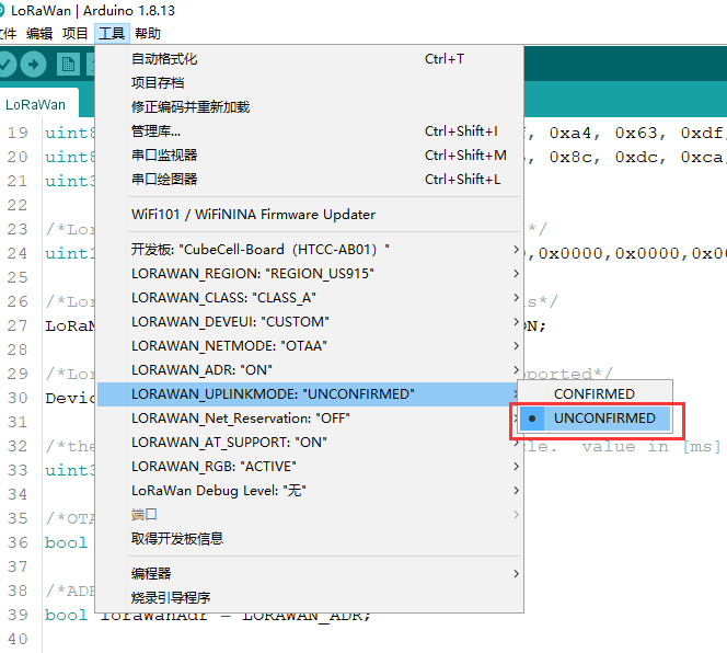
The easiest sketch to demonstrate the problem is the LoraWan example. I’ve changed the OTAA/ABP, the channel mask (0x0300 to use the first two channels in band 2) and added Serial.println statements to track processing. If I take out the prints the data in TTN is identical (so no prepareTxFrame is being processed) and the duty cycle isn’t correct so I’m guessing Serial processing isn’t affecting things.

Here are my current board details (I’ve also tried using AT+ for the duty cycle without luck).

14:33:16.619 -> Copyright @2019-2020 Heltec Automation.All rights reserved.
14:33:16.891 ->
14:33:16.891 -> AT Rev 1.3
14:33:16.891 -> +AutoLPM=1
14:33:16.891 ->
14:33:16.891 -> +LORAWAN=1
14:33:16.891 ->
14:33:16.891 -> +KeepNet=0
14:33:16.891 -> +OTAA=1
14:33:16.891 -> +Class=A
14:33:16.891 -> +ADR=0
14:33:16.891 -> +IsTxConfirmed=0
14:33:16.891 -> +AppPort=2
14:33:16.891 -> +DutyCycle=60000
14:33:16.891 -> +ConfirmedNbTrials=4
14:33:16.891 -> +ChMask=000000000000000000000300
14:33:16.925 -> +DevEui=7C9EBDXXXXXXXXX(For OTAA Mode)
14:33:16.925 -> +AppEui=70B3D5XXXXXXXXXX(For OTAA Mode)
14:33:16.925 -> +AppKey=56938E3666EXXXXXXXXXXXXXXXXXXX(For OTAA Mode)
14:33:16.925 -> +NwkSKey=00000000000000000000000000000000(For ABP Mode)
14:33:16.925 -> +AppSKey=00000000000000000000000000000000(For ABP Mode)
14:33:16.925 -> +DevAddr=00000000(For ABP Mode)
14:33:16.925 ->
14:33:16.925 ->

Than you in advance. I really hope I’m doing something stupid.:joy:

maybe incorrectly. If you use the 0th channel and the 1st channel, the correct one should be: 0x0003

BTW, maybe you can post your Loop() function of your LORAWAN code.

Good day Jason. Thanks for the reply.

Here is the loop(), it is the same one in all of your examples:

void loop()
{
  switch ( deviceState )
  {
    case DEVICE_STATE_INIT:
      {
#if(LORAWAN_DEVEUI_AUTO)
        LoRaWAN.generateDeveuiByChipID();
#endif
#if(AT_SUPPORT)
        getDevParam();
#endif
        printDevParam();
        LoRaWAN.init(loraWanClass, loraWanRegion);
        deviceState = DEVICE_STATE_JOIN;
        break;
      }
    case DEVICE_STATE_JOIN:
      {
        LoRaWAN.join();
        break;
      }
    case DEVICE_STATE_SEND:
      {
        prepareTxFrame( appPort );
        LoRaWAN.send();
        deviceState = DEVICE_STATE_CYCLE;
        break;
      }
    case DEVICE_STATE_CYCLE:
      {
        // Schedule next packet transmission
        txDutyCycleTime = appTxDutyCycle + randr( 0, APP_TX_DUTYCYCLE_RND );
        LoRaWAN.cycle(txDutyCycleTime);
        deviceState = DEVICE_STATE_SLEEP;
        break;
      }
    case DEVICE_STATE_SLEEP:
      {
        LoRaWAN.sleep();
        break;
      }
    default:
      {
        deviceState = DEVICE_STATE_INIT;
        break;
      }
  }
}

I am using US915 and TTN. They require band 2, at least in the US, so 0x0300 is correct here.

My issue isn’t connectivity – that is working fine. TTN is receiving messages…thousands of messages because I cannot increase the duty cycle to slow down the rate.

By the way, your HT-M00 was very simple to set up and has worked flawlessly.

Here is the same standard loop() with serial debug messages inserted:

void loop()
{
  switch ( deviceState )
  {
    case DEVICE_STATE_INIT:
      {
        if (ENABLE_SERIAL) {
          Serial.println("case INIT");
        }
#if(LORAWAN_DEVEUI_AUTO)
        LoRaWAN.generateDeveuiByChipID();
#endif
#if(AT_SUPPORT)
        getDevParam();
#endif
        printDevParam();
        LoRaWAN.init(loraWanClass, loraWanRegion);
        deviceState = DEVICE_STATE_JOIN;
        break;
      }
    case DEVICE_STATE_JOIN:
      {
        if (ENABLE_SERIAL) {
          Serial.println("case JOIN");
        }
        LoRaWAN.join();
        if (ENABLE_SERIAL) {
          Serial.println("JOIN complete");
        }
        break;
      }
    case DEVICE_STATE_SEND:
      {
        if (ENABLE_SERIAL) {
          Serial.println("case SEND");
        }
        prepareTxFrame( appPort );
        LoRaWAN.send();
        deviceState = DEVICE_STATE_CYCLE;
        break;
      }
    case DEVICE_STATE_CYCLE:
      {
        if (ENABLE_SERIAL) {
          Serial.println("case CYCLE");
        }
        // Schedule next packet transmission
        txDutyCycleTime = appTxDutyCycle + randr( 0, APP_TX_DUTYCYCLE_RND );
        LoRaWAN.cycle(txDutyCycleTime);
        deviceState = DEVICE_STATE_SLEEP;
        break;
      }
    case DEVICE_STATE_SLEEP:
      {
        if (ENABLE_SERIAL) {
          Serial.print(".");
        }
        LoRaWAN.sleep();
        break;
      }
    default:
      {
        if (ENABLE_SERIAL) {
          Serial.println("case default");
        }
        deviceState = DEVICE_STATE_INIT;
        break;
      }
  }
}

Here is the serial output with ENABLE_SERIAL = true. Not that every ‘.’ represents a pass through case DEVICE_STATE_SLEEP. I have uint32_t appTxDutyCycle = 30000; as the duty cycle.

Copyright @2019-2020 Heltec Automation.All rights reserved.
11:04:15.694 -> case INIT
11:04:15.728 -> 
11:04:15.728 -> AT Rev 1.3
11:04:15.728 -> +AutoLPM=1
11:04:15.728 -> 
11:04:15.728 -> +LORAWAN=1
11:04:15.728 -> 
11:04:15.728 -> +KeepNet=0
11:04:15.728 -> +OTAA=1
11:04:15.728 -> +Class=A
11:04:15.728 -> +ADR=0
11:04:15.728 -> +IsTxConfirmed=0
11:04:15.728 -> +AppPort=2
11:04:15.728 -> +DutyCycle=15000
11:04:15.728 -> +ConfirmedNbTrials=4
11:04:15.728 -> +ChMask=000000000000000000000300
11:04:15.728 -> +DevEui=7C9EBDFFFFFBA494(For OTAA Mode)
11:04:15.728 -> +AppEui=70B3D57ED003EFFC(For OTAA Mode)
11:04:15.728 -> +AppKey=56938E3666E1735BC449B37EB2D59191(For OTAA Mode)
11:04:15.728 -> +NwkSKey=00000000000000000000000000000000(For ABP Mode)
11:04:15.761 -> +AppSKey=00000000000000000000000000000000(For ABP Mode)
11:04:15.761 -> +DevAddr=00000000(For ABP Mode)
11:04:15.761 -> 
11:04:15.761 -> 
11:04:15.761 -> LoRaWAN US915 Class A start!
11:04:15.761 -> 
11:04:15.897 -> case JOIN
11:04:15.897 -> joining...TX on freq 904100000 Hz at DR 3 power 20 dBm
11:04:15.897 -> JOIN complete
11:04:15.897 -> ..........................................RX on freq 923900000 Hz at DR 13
11:04:20.974 -> ..................RX on freq 923300000 Hz at DR 8
11:04:21.989 -> ............TX on freq 903900000 Hz at DR 0 power 20 dBm
11:04:22.935 -> ..........................................RX on freq 923300000 Hz at DR 10
11:04:28.345 -> ..................RX on freq 923300000 Hz at DR 8
11:04:29.359 -> ............TX on freq 904100000 Hz at DR 3 power 20 dBm
11:04:29.934 -> ..........................................RX on freq 923900000 Hz at DR 13
11:04:35.007 -> ..................RX on freq 923300000 Hz at DR 8
11:04:36.022 -> ............TX on freq 903900000 Hz at DR 0 power 20 dBm
11:04:36.970 -> ..........................................RX on freq 923300000 Hz at DR 10
11:04:42.381 -> ..................RX on freq 923300000 Hz at DR 8
11:04:43.396 -> ............TX on freq 903900000 Hz at DR 3 power 20 dBm
11:04:43.972 -> ..........................................RX on freq 923300000 Hz at DR 13
11:04:49.043 -> ..................RX on freq 923300000 Hz at DR 8
11:04:50.062 -> ............TX on freq 904100000 Hz at DR 0 power 20 dBm
11:04:51.009 -> ..........................................RX on freq 923900000 Hz at DR 10
11:04:56.425 -> ..................RX on freq 923300000 Hz at DR 8
11:04:57.441 -> ............TX on freq 903900000 Hz at DR 3 power 20 dBm
11:04:58.016 -> ..........................................RX on freq 923300000 Hz at DR 13
11:05:03.090 -> ..................RX on freq 923300000 Hz at DR 8
11:05:04.104 -> ............TX on freq 904100000 Hz at DR 0 power 20 dBm
11:05:05.018 -> ..........................................RX on freq 923900000 Hz at DR 10
11:05:10.458 -> ..................RX on freq 923300000 Hz at DR 8
11:05:11.469 -> ............TX on freq 904100000 Hz at DR 3 power 20 dBm
11:05:12.044 -> ..........................................RX on freq 923900000 Hz at DR 13
11:05:17.120 -> ..................RX on freq 923300000 Hz at DR 8
11:05:18.133 -> ............TX on freq 903900000 Hz at DR 0 power 20 dBm
11:05:19.077 -> ..........................................RX on freq 923300000 Hz at DR 10
11:05:24.490 -> ..................RX on freq 923300000 Hz at DR 8
11:05:25.507 -> ............TX on freq 904100000 Hz at DR 3 power 20 dBm
11:05:26.084 -> ..........................................RX on freq 923900000 Hz at DR 13
11:05:31.160 -> ..................RX on freq 923300000 Hz at DR 8
11:05:32.173 -> ............TX on freq 903900000 Hz at DR 0 power 20 dBm
11:05:33.120 -> ..........................................RX on freq 923300000 Hz at DR 10
11:05:38.536 -> ..................RX on freq 923300000 Hz at DR 8
11:05:39.549 -> ............TX on freq 904100000 Hz at DR 3 power 20 dBm
11:05:40.122 -> ..........................................RX on freq 923900000 Hz at DR 13
11:05:45.193 -> ..................RX on freq 923300000 Hz at DR 8

And here is the same serial output with debug messages off and the same duty cycle of 30 seconds.

11:14:50.583 -> Copyright @2019-2020 Heltec Automation.All rights reserved.
11:14:50.863 -> 
11:14:50.863 -> AT Rev 1.3
11:14:50.863 -> +AutoLPM=1
11:14:50.863 -> 
11:14:50.863 -> +LORAWAN=1
11:14:50.863 -> 
11:14:50.863 -> +KeepNet=0
11:14:50.863 -> +OTAA=1
11:14:50.863 -> +Class=A
11:14:50.863 -> +ADR=0
11:14:50.863 -> +IsTxConfirmed=0
11:14:50.863 -> +AppPort=2
11:14:50.863 -> +DutyCycle=30000
11:14:50.863 -> +ConfirmedNbTrials=4
11:14:50.863 -> +ChMask=000000000000000000000300
11:14:50.863 -> +DevEui=7C9EBDFFFFFBA494(For OTAA Mode)
11:14:50.903 -> +AppEui=70B3D57ED003EFFC(For OTAA Mode)
11:14:50.903 -> +AppKey=56938E3666E1735BC449B37EB2D59191(For OTAA Mode)
11:14:50.903 -> +NwkSKey=00000000000000000000000000000000(For ABP Mode)
11:14:50.903 -> +AppSKey=00000000000000000000000000000000(For ABP Mode)
11:14:50.903 -> +DevAddr=00000000(For ABP Mode)
11:14:50.903 -> 
11:14:50.903 -> 
11:14:50.903 -> LoRaWAN US915 Class A start!
11:14:50.903 -> 
11:14:51.023 -> joining...TX on freq 903900000 Hz at DR 3 power 20 dBm
11:14:56.103 -> RX on freq 923300000 Hz at DR 13
11:14:57.143 -> RX on freq 923300000 Hz at DR 8
11:14:58.064 -> TX on freq 904100000 Hz at DR 0 power 20 dBm
11:15:03.504 -> RX on freq 923900000 Hz at DR 10
11:15:04.504 -> RX on freq 923300000 Hz at DR 8
11:15:05.064 -> TX on freq 904100000 Hz at DR 3 power 20 dBm
11:15:10.144 -> RX on freq 923900000 Hz at DR 13
11:15:11.144 -> RX on freq 923300000 Hz at DR 8
11:15:12.104 -> TX on freq 903900000 Hz at DR 0 power 20 dBm
11:15:17.544 -> RX on freq 923300000 Hz at DR 10
11:15:18.544 -> RX on freq 923300000 Hz at DR 8
11:15:19.104 -> TX on freq 903900000 Hz at DR 3 power 20 dBm
11:15:24.184 -> RX on freq 923300000 Hz at DR 13
11:15:25.184 -> RX on freq 923300000 Hz at DR 8
11:15:26.144 -> TX on freq 904100000 Hz at DR 0 power 20 dBm
11:15:31.585 -> RX on freq 923900000 Hz at DR 10
11:15:32.585 -> RX on freq 923300000 Hz at DR 8
11:15:33.145 -> TX on freq 904100000 Hz at DR 3 power 20 dBm
11:15:38.225 -> RX on freq 923900000 Hz at DR 13
11:15:39.225 -> RX on freq 923300000 Hz at DR 8
11:15:40.185 -> TX on freq 903900000 Hz at DR 0 power 20 dBm
11:15:45.625 -> RX on freq 923300000 Hz at DR 10
11:15:46.625 -> RX on freq 923300000 Hz at DR 8
11:15:47.185 -> TX on freq 904100000 Hz at DR 3 power 20 dBm
11:15:52.265 -> RX on freq 923900000 Hz at DR 13
11:15:53.265 -> RX on freq 923300000 Hz at DR 8
11:15:54.225 -> TX on freq 903900000 Hz at DR 0 power 20 dBm
11:15:59.625 -> RX on freq 923300000 Hz at DR 10
11:16:00.665 -> RX on freq 923300000 Hz at DR 8
11:16:01.225 -> TX on freq 903900000 Hz at DR 3 power 20 dBm
11:16:06.305 -> RX on freq 923300000 Hz at DR 13
11:16:07.305 -> RX on freq 923300000 Hz at DR 8
11:16:08.225 -> TX on freq 904100000 Hz at DR 0 power 20 dBm
11:16:13.665 -> RX on freq 923900000 Hz at DR 10
11:16:14.705 -> RX on freq 923300000 Hz at DR 8
11:16:15.265 -> TX on freq 903900000 Hz at DR 3 power 20 dBm

hi,
Maybe you can try the following two methods separately:

  1. change to “unconfirmed”.

  2. change to 1.

The TTN server has a limit on the number of uplinks for each node. When you reach a certain number of upstream frames, TTN will not send downlink any more.

16:06:36.348 -> joining…TX on freq 903900000 Hz at DR 3 power 20 dBm
16:06:41.423 -> RX on freq 923300000 Hz at DR 13
16:06:41.965 -> joined

Success!

After trying everything else I deleted the device in TTN and added it back again exactly the same except I generated a new device ID. It started working immediately.

Sometimes you’re the Shih Tzu, sometimes you’re the tree.

Thank you for your help Jason.

1 Like