Automazione per pompa

Sto scaricando i pacchetti

esp32:esp32-arduino-libs@idf-release_v5.5-b66b5448-v1

esp32:esp-x32@2411

esp32:xtensa-esp-elf-gdb@16.2_20250324

esp32:esp-rv32@2411

Failed to install platform: ‘esp32:esp32:3.3.0’.

Error: 2 UNKNOWN: stream error: stream ID 7; PROTOCOL_ERROR; received from pee

quale errore?
copia e incolla il messaggio di errore?

That’s an install error with downloading - just try it again.

It’s the compile errors that are a problem.

Try to think MUCH HARDER about your posts - it saves so much time if you tell us what an error is rather than that there was an error.

I’m the person that tests RadioLib for LoRa/LoRaWAN - so I know it works as @horace says - but you must get the basics sorted and Google error messages for such basic stuff.

Scusa stavo solo caricando il core Esp32 di espressif ma nel mezzo del caricamento mi ha dato l’errore che ho postato prima

iI have never seen that particular error message
what installation instructions are you following?
have a look at ESpressif Getting Started - About Arduino ESP32

stavo istallando dal gestore schede il core Esp32 3.3.0 come avevi indicato

Ho caricato il codice “Trasmit interrupt” e questo e’ l’output del monitor seriale.

looks like your program is not communicating with the LoRa SX1262 radio

did you setup the Heltec LoRa V3 pins correctly, e.g.

// Heltec LoRa V3  SX1262 has the following connections:
// NSS pin:   8
// DIO1 pin:  14
// NRST pin:  12
// BUSY pin:  13
SX1262 radio = new Module(8, 14, 12, 13);

and the frequency for your country?

  int state = radio.begin(868.0);

rather than posting screen images which are difficult to read copy the code and message text and post it

Questo e’ lo schema di heltec lora 32 (Versione 3.2) la mia
Guardando lo schema credo che effettivamente devo cambiare i pin

Questo e’ il codice che ho caricato
/*

RadioLib SX126x Transmit with Interrupts Example

This example transmits LoRa packets with one second delays

between them. Each packet contains up to 256 bytes

of data, in the form of:

  • Arduino String

  • null-terminated char array (C-string)

  • arbitrary binary data (byte array)

Other modules from SX126x family can also be used.

For default module settings, see the wiki page

https://github.com/jgromes/RadioLib/wiki/Default-configuration#sx126x---lora-modem

For full API reference, see the GitHub Pages

https://jgromes.github.io/RadioLib/

*/

// include the library

#include <RadioLib.h>

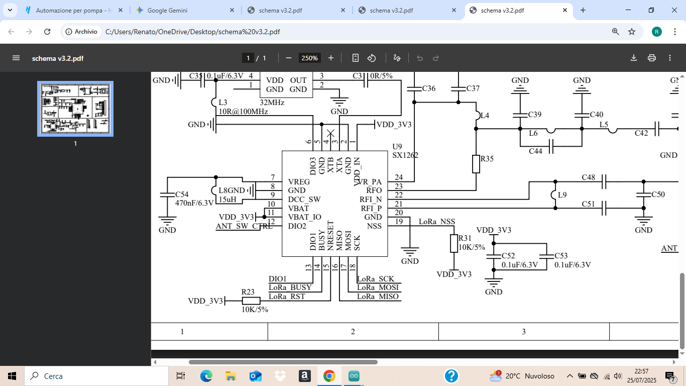
// SX1262 has the following connections:

// NSS pin: 19

// DIO1 pin: 13

// NRST pin: 15

// BUSY pin: 14

SX1262 radio = new Module(19, 13, 15, 14);

// or detect the pinout automatically using RadioBoards

// https://github.com/radiolib-org/RadioBoards

/*

#define RADIO_BOARD_AUTO

#include <RadioBoards.h>

Radio radio = new RadioModule();

*/

// save transmission state between loops

int transmissionState = RADIOLIB_ERR_NONE;

// flag to indicate that a packet was sent

volatile bool transmittedFlag = false;

// this function is called when a complete packet

// is transmitted by the module

// IMPORTANT: this function MUST be ‘void’ type

// and MUST NOT have any arguments!

#if defined(ESP8266) || defined(ESP32)

ICACHE_RAM_ATTR

#endif

void setFlag(void) {

// we sent a packet, set the flag

transmittedFlag = true;

}

void setup() {

Serial.begin(9600);

// initialize SX1262 with default settings

Serial.print(F("[SX1262] Initializing … "));

int state = radio.begin(868.0);

if (state == RADIOLIB_ERR_NONE) {

Serial.println(F("success!"));

} else {

Serial.print(F("failed, code "));

Serial.println(state);

while (true) { delay(10); }

}

// set the function that will be called

// when packet transmission is finished

radio.setPacketSentAction(setFlag);

// start transmitting the first packet

Serial.print(F("[SX1262] Sending first packet … "));

// you can transmit C-string or Arduino string up to

// 256 characters long

transmissionState = radio.startTransmit(“Hello World!”);

// you can also transmit byte array up to 256 bytes long

/*

byte byteArr[] = {0x01, 0x23, 0x45, 0x67,

                  0x89, 0xAB, 0xCD, 0xEF};

state = radio.startTransmit(byteArr, 8);

*/

}

// counter to keep track of transmitted packets

int count = 0;

void loop() {

// check if the previous transmission finished

if(transmittedFlag) {

// reset flag

transmittedFlag = false;

if (transmissionState == RADIOLIB_ERR_NONE) {

  // packet was successfully sent

  Serial.println(F("transmission finished!"));

  // NOTE: when using interrupt-driven transmit method,

  //       it is not possible to automatically measure

  //       transmission data rate using getDataRate()

} else {

  Serial.print(F("failed, code "));

  Serial.println(transmissionState);

}

// clean up after transmission is finished

// this will ensure transmitter is disabled,

// RF switch is powered down etc.

radio.finishTransmit();

// wait a second before transmitting again

delay(1000);

// send another one

Serial.print(F("[SX1262] Sending another packet ... "));

// you can transmit C-string or Arduino string up to

// 256 characters long

String str = "Hello World! #" + String(count++);

transmissionState = radio.startTransmit(str);

// you can also transmit byte array up to 256 bytes long

/*

  byte byteArr[] = {0x01, 0x23, 0x45, 0x67,

                    0x89, 0xAB, 0xCD, 0xEF};

  transmissionState = radio.startTransmit(byteArr, 8);

*/

}

}

Questo e’ il serial monitor
Messaggio (premi Enter per inviare il messaggio a ‘Heltec WiFi LoRa 32(V3) / Wireless shell(V3) / Wireless stick lite (V3)’ on ‘COM3’)

A capo (NL)

9600 baud

.��� ��r��[SX1262] Initializing … failed, code -2

ESP-ROM:esp32s3-20210327

Build:Mar 27 2021

rst:0x1 (POWERON),boot:0x8 (SPI_FAST_FLASH_BOOT)

SPIWP:0xee

mode:DIO, clock div:1

load:0x3fce3808,len:0x44c

load:0x403c9700,len:0xbe4

load:0x403cc700,len:0x2a68

entry 0x403c98d4

Allora ho corretto i pin in 8-14-12-13 e funziona sia transmitter interrupt che receive interrupt.
Ora sarebbe bello riuscire a far funzionare lo schermo oled e l’automazione che mi serve (galleggiante e pompa)

The code doesn’t automatically change to suit the board it’s on. And the documentation for RadioLib clearly states that the pins need setting. And there is a RadioBoards library that will do it for you.

Why have you posted a screen shot for something we all have access to? It doesn’t help.

And … success … presumably you slowed down enough to look at what you were doing. There is even a reference to the RadioBoards library in the code.

Really? You think the volunteers answering here have that much patience? Perhaps you should get the sensor & the relay working before making it pretty. At least then you have the functionality you want. But as we have NO details on the float or pump, we are back to asking a thousand questions before you tell us the information needed to help you.

:man_shrugging:

it is always worth having a look thru the library examples to see if there is code to test basic module functionality
e.g. have a look at File>Examples>Heltec ESP32 Dev-Boards>OLED>SimpleDemo

Voglio ringraziare tutti per la pazienza e per i suggerimenti che mi avete dato.Penso che un forum possa servire anche a fare si che chi non conosce bene l argomento ma al quale è molto appassionato possa imparare molto dai vostri consigli e suggerimenti.
Il galleggiante che dovrei usare è un semplice Off (livello alto) e On livello basso. Al livello basso trasmette un segnale all 'altra scheda che attiva una pompa fino al raggiungimento del livello alto.
Per avere dei feedback delle varie operazioni avevo pensato di usare lo schermo già incorporato nelle schede è qui che mi servirebbero dei suggerimenti per farlo funzionare dal momento che nemmeno con sketch di esempio (vedi hello world) non sono riuscito. Forse è un problema di librerie o di core.
Ricordo che gli sketch che ho caricato (Trasmitt interrupt e Receive interrupt funzionano.)
Le mie schede sono Heltec LoRa32 V3 (sotto versione 3.2
Grazie

Nope, more a learning curve problem.

You are working at Fiat 500 level, you need to reach Alfa Romeo to have a system you can rely on. There will be a few more cars along the way, some will be written off in spectacular crashes.

If you have yet to learn how to read an input using Arduino, then you are at pedal go-kart stage.

We’ve all been through this learning experience, it need not take long to get to a proficient level but you can’t learn it without the fundamentals, and no LLM (which is not AI) can do that for you. In fact a new study has shown that using a LLM makes things worse when learning something new. Teachers and trainers already knew this, but now it’s a fact!

using Arduino IDE V2.3.5 ESP32 core 3.3.0 Heltec ESP32 Dev-Boards V 2.1.4 setting Tolls>Board to Heltec WiFi LoRa32 (V3)
example File>Examples>Heltec ESP32 Dev-Boards>OLED>SimpleDemo compiles, link and loads and runs on my Heltec LoRa V3 without modification
image

how far is the level float from the pump?
i.e. do you a wireless connection?
when using LoRa remember the fair-use-policy

can you upload a schematic of the level float circuit?
remember the ESP32 uses 3.3V logic
how do you intend to activate the pump? e.g. a relay? what is the pumps current consumption?

Good call, but LoRa is not LoRaWAN so the FUP doesn’t apply but the legal duty cycle does.

Getting the display working will be a win for Rena, but thus far there’s no evidence that anything can be programmed without going back to Arduino 101.

Vedo dalla foto che la tua e’ una v3.1 la mia una V3.2
Cambia qualcosa?

Il galleggiante di livello non e’ altro che un semplice interruttore che apre e chiude a seconda del livello,Per quanto riguarda il rele’ utilizzerei un uscita per comandare un interfaccia che comanda il rele’. Il contatto pulito del rele’ lo uso per comandare la pompa.

No

No radio link between the pump and the float?

Just a radio link to tell you if the pump is running?