Any successful use of SPI.h?

Has anyone gotten SPI to work on the AB01 or AB02?

I’ve been unsuccessfully trying to read a SPI signal (with an AB01 v2) for a while now.

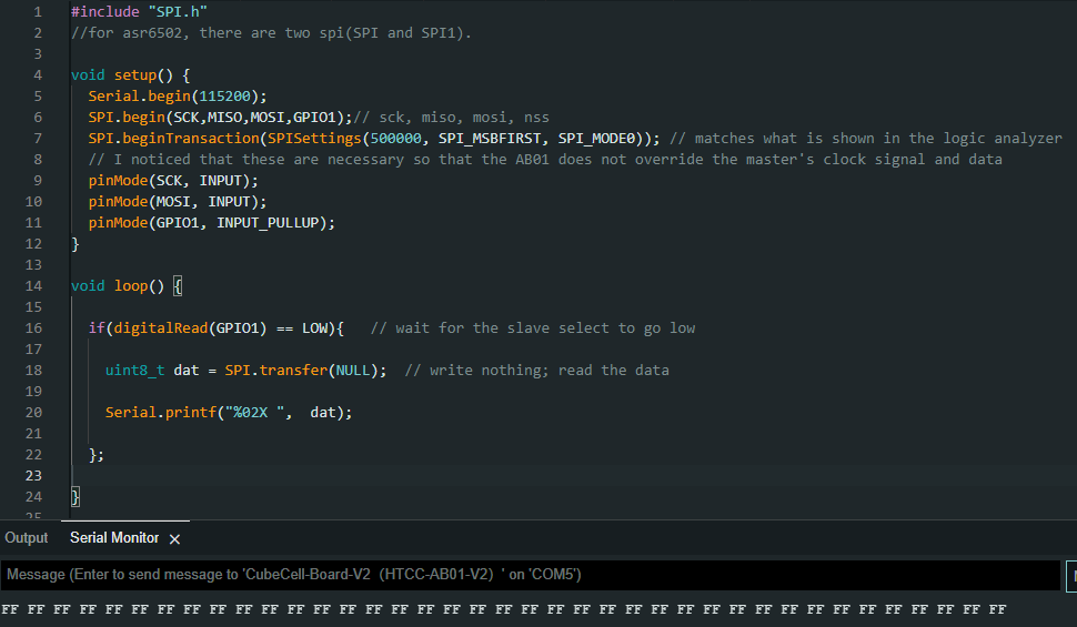
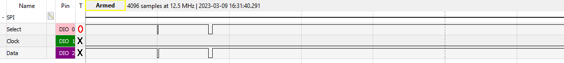
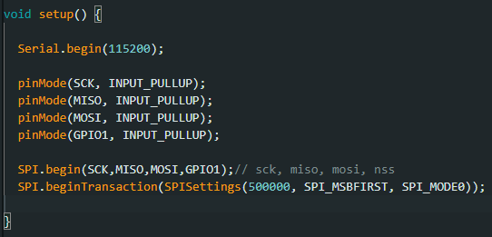
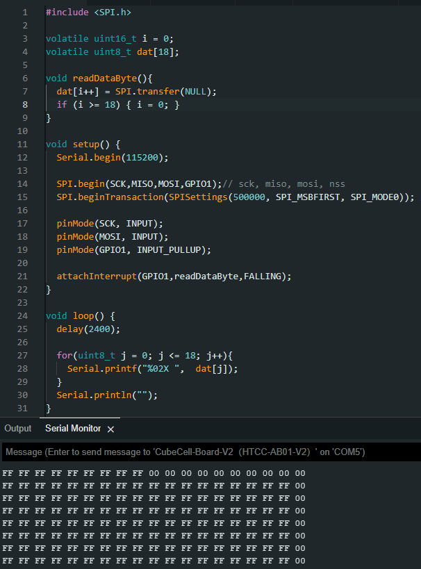
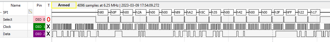
I’ve tried many things, ensuring mode/clock speed is correct, trying SPI and SPI1, trying GPIO pins 0-5 instead of the SPI pins, making sure I can see and decode the SPI signal using a logic analyzer, but no luck.

Also looked for working examples and success stories here and elsewhere online but can’t find any.

Has anyone gotten SPI to work on the AB01 or AB02?

The pins of AB01 cannot be mapped randomly. It is better to use the SPI pins marked on the pin map.

Thanks for your reply. Here are my connections:

Master -> AB01V2

Clock -> SCK
Data output -> MOSI
Slave Select -> GPIO1
Ground -> GND

My logic analyzer SPI decoder reads the correct series of 18 bytes, always starting with 0x80:

But the AB01V2 produces five 0xFF bytes instead of the 18 bytes of data.

Here is my code.

Am I doing something wrong?

You use AB01 as the slave, right?
Check whether the SPI mode corresponds to the host.

Yes, correct, I’m trying to use it as slave. The polarities and timings correspond to Mode 0, so that’s what I’m using. But I also tried all the other modes just to be sure. None of them work.

Set all gateways to pull-up input, and then initialize SPI.

When I set everything to pull-up inputs first, then the signals from the master disappear and nothing is read:

image

To make sure the master signals don’t disappear, I have to set pins to INPUT and INPUT_PULLUP after initializing SPI like this.


… but then the output is incorrect, just FF and 00

That script allows the master signals (but doesn’t read the data)

@dirk did you ever get this working?

ArduCAM OV2640 uses SPI and I2C, and I got it working on an HTCC-AB01 board.

@desechar
podrias compartir las conexiones de que utilizaste para SPI