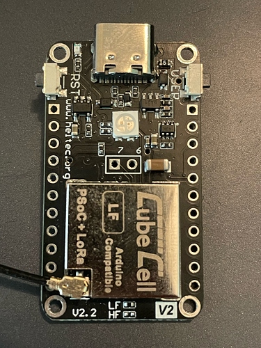
Analog Read CubeCell

Hello I¡m trying to do an analog read from a temperature sensor TMP36, so in arduino the conversion for the analog read is 5/1024 I have observed that it not the same for the CubeCell Board, how do I have to adjust this value to get the correct conversion for make a right analog read?

Here is my program

int Sensor = ADC;

void setup() {
Serial.begin(9600);
pinMode(Sensor, INPUT);
}

void loop() {
int lecture = analogRead(Sensor);
float voltage = 5.0/1024 * lecture;
float temp = voltage * 100 - 50;
Serial.print(“Voltage --> “);
Serial.print(voltage);
Serial.println(” V”);
Serial.print("Temperature --> ");
Serial.print(temp);
Serial.println(“ºC”);
delay(2000);
Serial.print("Lecture–> ");
Serial.println(lecture);
delay(2000);

}

And this is what I’m getting:

Voltage --> 11.05 V
Temperature --> 1055.47ºC
Lecture–> 2264

And I should get (Arduino Uno using —> 5/1024):

Voltage --> 0.77 V
Temperature --> 26.66ºC
Lecture–> 157

analogRead() return the value in mV directly. The max input voltage can be read is 2399 mV.

1 Like

I believe the Cubecel is a 12 bit chip. The conversion should be 4095 , not 1023. And is the voltage may also change to 3.3 volts. so your divvider would be 3.3/4095 rather than 5/1023.
I havent researched it exactly so am just guessing but follow this path.

Has this ever been resolved? My results with analog read are rubbish so I’m wondering what’s the solution.

We have made an update and have detailed instructions. You can refer to it.


Hi I am trying to get the ADC on this Cubecell board working.
Very simply I have a voltage divider of two 10k resistors in series across the 3.3v pin and ground and the centre connected to the ADC pin. The voltage reads 1.65v with my multimeter.
The Cubecell via Arduino serial monitor reads Voltage 0, Level about 195 but it fluctuates.

I am using your code above. https://github.com/HelTecAutomation/CubeCell-Arduino/blob/master/libraries/Basics/examples/ADC/ADC/ADC.ino

I have tried removing the BR1 resistor from the board, but it made no difference. I have tried on 2 different HTCC-AB01 V2.2 and they both don’t display the correct results.

What can I try now?

In response to your query relating to the ADC pin [Htcc-ab01-v2 color problem], the one ‘accessible’ ADC is connected to the pin so labelled. It can be identified as ADC in a sketch.

I have used the ADC on an earlier version of the CubeCell Dev-Board, but not yet on the V2.2 boards that I have. Given that the V2 boards now use the ASR6502 processor, I would not have expected them to be any different to the CubeCell Plus Dev-Board, the fact that only one ADC is available on the former notwithstanding. On this basis, and for what it’s worth, an application using the ADC on a CubeCell Plus Dev-Board, reading wind direction from an anemometer, is described here (circuit diagram and code included).

I can confirm that the ADC seems to not work on the new V2 board.
I tested the earlier board and the code and hardware works as expected.

I have not yet delved in to removing components as im waiting to hear back from support before I do just in case there is something I am missing.

Again, for what it’s worth, I am using the ADCs on a V2 board (but an early V2 board, not a V2.2 board, although I have no reason to believe that there should be any difference, since both use the same ASR6502 processor). As noted in another thread, I have just run up a sketch on a V2.2 board and it is reading the battery voltage as expected. The V2 board that I have running in an application, in addition to reading the battery voltage through the ADC dedicated to that function, also reads an external voltage through the ADC pin on the board.

Remember that the V2 board uses the ASR6502 processor, which has three ADCs (although only two are used on the CubeCell board, one specifically for reading the battery voltage and the other being broken out to the ADC pin on the board).