AM02 Module Plus - Custom PCB - Minimal circuit arduino compatible

Thank you for your response.
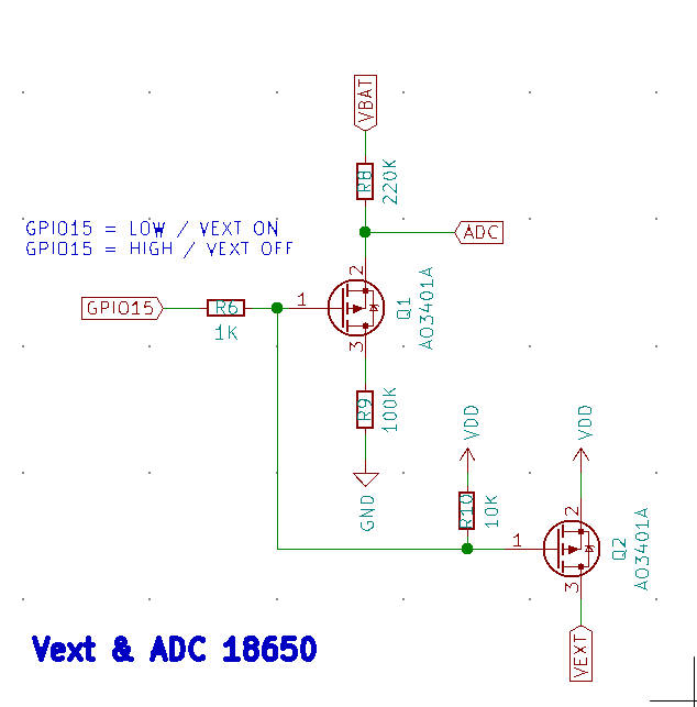
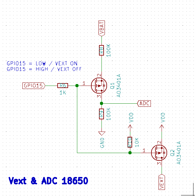
So by design, when GPIO15 is LOW, V(ADC)= with my battery 3.7V to 4.2V. I don’t understand with a circuit is propose knowing that ADC can’t support more than 2.4V. What kind of damages can it cause? Maybe more power consumption?

I really want to be sure for my next PCB design and be sure that any mistake is done with the recommended manufacturer design.
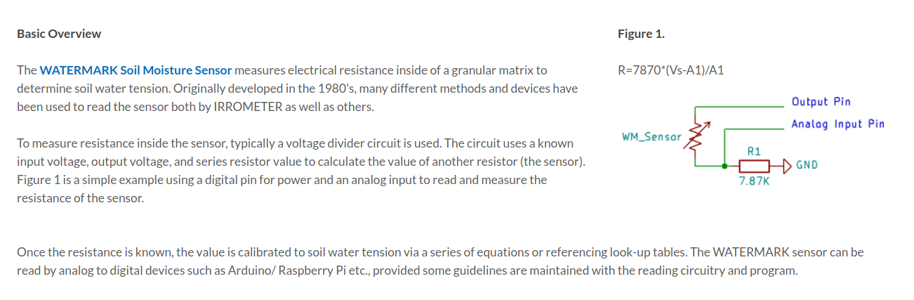
I also need to use one capacitive sensor with GPIO as output and ADC and on the Arduino example the simplest way to wire the sensor is to use GPIO as output and ADC for reading. With the 2.4V limitation, how can I use this one? http://community.heltec.cn/t/cubecell-and-second-serial-port/693/9
Thank you to both of you
@ksckung @jasonXu

What kind of damages can it cause? Maybe more power consumption?

No one knows. In my test, it shows 17uA more(153%) when the battery voltage at 4.2V.
I recommend modify the circuit, measure, and share the result before next PCB design.

The IO voltage of AM02 is 3.3V but Arduino is 5V.
The ADC input voltage is limited to 2.4V with 1.2V reference but Arduino is both 5V.

First, you need to test it work/not under AM02 3.3V GPIO output.
Then check the voltage range of sensor analog output.
If it is out of range, use opamp to buffer and attenuate the signal.

At least, I know how a voltage divider is used! I am disappointed to use the HTCC-AM02 wich is pretty sexy for low power and 3xADC pins.
I’ll try to test my sensor with GPIO as input, maybe it will be a success.


For now, I made a circuit with another circuit with a 555timer. It seems that reading the sensor resistance is more reliable instad the frequency reading and need less conversion to get the value. Too bad … Opamp is also a new domain for me, hard to start from scratch.
I hope that Heltec can improve the ADC input voltage to a more usable one >2.4V (like Arduino’s) on the next modules they produce. Maybe they will tease a date or specifications !
Again @ksckung @jasonXu thank for your help!

@ksckung
I mesure yesterday, it seems that I have 17µA consumption with a 3.8V battery.
Maybe I should try to replace resistors on ADC channels with 10K as you propose here and mesure again.
http://community.heltec.cn/t/power-consumption-in-sleep-mode-vbat-battery-powered/2889/5?u=alexfr

For my sensor, I find a device that I want to design on the PCB. No idead what’s in the black box!
https://www.irrometer.com/pdf/supportmaterial/sensors/voltage-WM-chart.pdf
https://www.irrometer.com/pdf/sensors/405%20Voltage%20Adapter%20&%20Isolator-WEB.pdf
https://www.emesystems.com/smx/documents/SMX_2018.pdf
They said in the doc

ELECTRICAL:3.2 - 30 volt, 1.5 mA input, polarity protected / 0 - 2.8 volt output, linear / 0 - 239 cb (kPa) = 0 to 2.8 volts linear. "

I will post news if my power consumption goes to 17µA to less.
Take care.

I didn’t have AM02, please check and test the Voltage vs raw reading first.
In CubeCell – Dev-Board ,I use 100k +NMOS+100k and connect ADC pin to the Drain of NMOS
image

The Sleep current is around 6.322uA with 3.7V power supply.
SCREEN_111

Here is the voltage on ADC pin when the program turn on the PMOS, Battery voltage is ~4.16V

Hello Sir,
based on your last schematic, I replace R16 & R17 with 100K resistor.
I disconnect ADC from source to connect it to the drain’s Fet. Still getting around 16µA in deepsleep but getting 1.96V in the ADC with a 3.9V battery. :slight_smile:
I don’t try to reach the 3.5µA on 3.3V power because my device only runs on battery.
I think it’s a good confirguration for my next PCB!

Before (based on the Heltec recommanded design):

After (based on @ksckung design):

@AlexFR
6.322uA with 3.7V is power via battery port.

Hello @ksckung,
I am using the HDC2080 but I encounter problem to running the example test of the library
HDC2080 lib

  • In fact I am using the second I²C on the HTCC-AM02 (pins 24&25)
  • Vext is controlling the HDC2080 as you recommand.
    This is the example Arduino example
    I think the example use the first I²C bus by defaut.

How can I simply declare to use Wire.begin(1000000,1); and Wire.end ?

Thank you
Alex

I succesfully find the adress of the HDC2080 with this example based on the “I2C_scan” from Heltec. =0x40

#include “Arduino.h”
#include “Wire.h”
void setup()
{
Serial.begin(115200);
Wire.begin(1000000,1);
pinMode(GPIO5,OUTPUT);
digitalWrite(GPIO5,LOW);//set GPIO5 to high
}
void loop()
{
byte error, address;
int nDevices;
Serial.println(“Scanning…”);
nDevices = 0;
for(address = 1; address < 127; address++ )
{
Wire.beginTransmission(address);
error = Wire.endTransmission();
if (error == 0)
{
Serial.print(“I2C device found at address 0x”);
if (address<16)
Serial.print(“0”);
Serial.print(address,HEX);
Serial.println(" !");
nDevices++;
}
else if (error==4)
{
Serial.print(“Unknown error at address 0x”);
if (address<16)
Serial.print(“0”);
Serial.println(address,HEX);
}
}
if (nDevices == 0)
Serial.println(“No I2C devices found\n”);
else
Serial.println(“done\n”);
delay(5000);
}

And response in the console

Scanning…
I2C device found at address 0x40 !
done

The pins 24 and 25 of AM02 are the second group of IIC. You can use Wire.begin(GPIO9,GPIO8) or Wire1.begin() to enable the second group of IIC.

Hello @shaffer, I just solved my problem.
I edited the library for the sensor HDC2080 https://github.com/tinkeringtech/HDC2080_breakout
I just edited the hdc2080.cpp file at line 44.

void HDC2080::begin(void)
{
Wire.begin();
}

became

void HDC2080::begin(void)
{
Wire.begin(SDA1,SCL1,500000);
}

It use now the pins GPIO8,GPIO9 as you know.
Thanks for your help!