AB02S Display stop working when Settin LED. Hardware Issue? **SOLVED**

Hello everybody and thanks in advance for your help.

I am testing the basics feature of the AB02S… And I having a veru strange issue… I am using one switch in the GPIO07, and one led in the GPIO10. I am also using hte OLED to show the Switch Status… When I do not operate the LED, the OLED works just fine. But as soon as I include the swithc veryfication rutine to set the Led on and off the OLED does black and never returns… It is really strange, as soon as a digitalWrite function is used, the OLED goes black…

Any idea of what could be happening?

Thank you all in advance
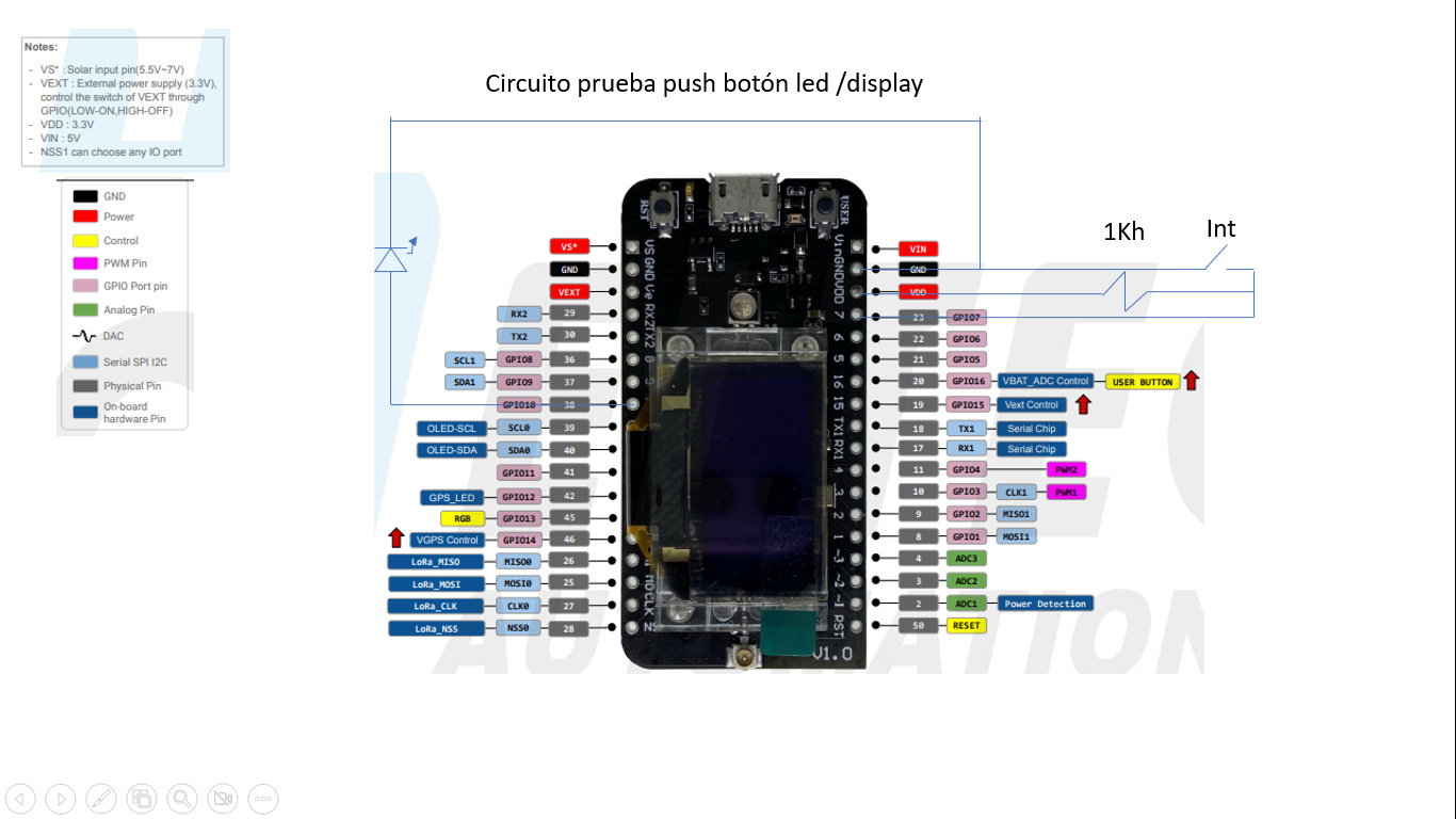
This is the wiring

And this is the code:

#include <Wire.h>

#include “HT_SSD1306Wire.h”

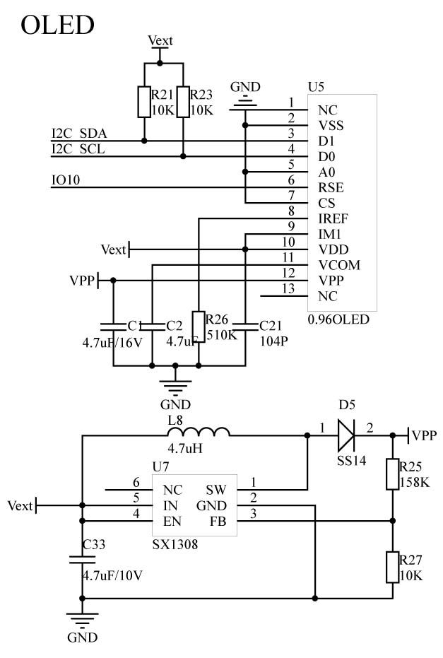
SSD1306Wire display(0x3c, 500000, SDA, SCL, GEOMETRY_128_64, GPIO10); // addr , freq , SDA, SCL, resolution , rst

// constants won’t change. They’re used here to set pin numbers:

const int buttonPin = GPIO7; // the number of the pushbutton pin

const int ledPin = GPIO10; // the number of the LED pin

// variables will change:

int buttonState = 0; // variable for reading the pushbutton status

int counter = 1;

void VextON(void)

{

pinMode(Vext,OUTPUT);

digitalWrite(Vext, LOW);

}

void VextOFF(void) //Vext default OFF

{

pinMode(Vext,OUTPUT);

digitalWrite(Vext, HIGH);

}

void setup() {

// initialize the LED pin as an output:

pinMode(ledPin, OUTPUT);

// initialize the pushbutton pin as an input:

pinMode(buttonPin, INPUT);

// initialize display

Serial.begin(115200);

VextON();

delay(100);

display.init();

display.clear();

display.display();

display.setTextAlignment(TEXT_ALIGN_CENTER);

display.setFont(ArialMT_Plain_16);

display.drawString(64, 32-16/2, “Iniciando…”);

display.display();

delay(2000);

}

void loop() {

// put your main code here, to run repeatedly:

// read the state of the pushbutton value:

buttonState = digitalRead(buttonPin);

// Info to be displayed

char str[30];

display.clear();

display.setFont(ArialMT_Plain_16);

sprintf(str,“Contador = (%d)”, counter);

display.setTextAlignment(TEXT_ALIGN_LEFT);

display.drawString(0, 0, str);

sprintf(str,“Interruptor = (%d)”, buttonState);

display.setTextAlignment(TEXT_ALIGN_LEFT);

display.drawString(0, 15, str);

// write the buffer to the display

display.display();

// check if the pushbutton is pressed. If it is, the buttonState is HIGH:

if (buttonState == HIGH) {

// turn LED on:

//digitalWrite(ledPin, HIGH);

} else {

// turn LED off:

//digitalWrite(ledPin, LOW);

}

delay(500);

counter++;

}

I think you’ll find that GPIO10 is the OLED Reset pin. Try using a different pin for your LED.

@UniquePete you looks to have a good understanding for the product. Would you know how to load the original factory firmware in case of any mistake?

Thanks in advacne for your help

Also @UniquePete, this is the Heltec pinout… I choose the GPIO10 becouse it seems to be free

But I will try another one as you said…

Also the example code is not completely commented and ther is not an extensive documentation…

I included this code becouse is included in all the examples using the oled. But I do not undestand… It seems to me that Vext is controlling the OLED…

void VextON(void)

{

pinMode(Vext,OUTPUT);

digitalWrite(Vext, LOW);

}

void VextOFF(void) //Vext default OFF

{

pinMode(Vext,OUTPUT);

digitalWrite(Vext, HIGH);

Do you undestarnd?

Thank you in advance fro your help!

By the way @UniquePete, it working perfectly, just as you said… Thank you… So pin GPIO10 controls the OLED!

Two things. First, yes, some of the documentation is not great and sometimes it helps to be working with several different [Heltec] boards—patterns start to emerge. In this case, the AB02S is a variant of the AB02, so if you look at the pinout diagram for the AB02 you will see that GPIO10 is labelled as OLED-RESET.


The other place to look is at the relevant pins_arduino.h help files (in this case, located down in the Arduino/hardware/CubeCell/CubeCell/variants folder), although that doesn’t help much in this case.

As for Vext controlling the OLED display, the OLED display is on an I2C bus and it would not be entirely surprising if Vext controlled power, not only to the Vext pin but also to the power rail of the I2C bus and thus the OLED display. Indeed, if you look at the AB02 schematic diagram—actually, it seems to have disappeared from the Docs & Resource area, but I’ve attached an image of the relevant section—you can see that this is precisely what is happening.


You can also see that GPIO10 is driving the OLED-RESET function.

I believe that this is just the Factory_Test sketch, located under the Examples menu (Examples > Basics > Factory_Test > Factory_Test_AB02S).

@UniquePete Thanks so much for you time and your help… I am going now to go to I2C, I have seen also many posts regarding this matter… Hopefully I will be able to make it work.
On documentation, it is quite a mess… I suposse that Heltec should be working on this… Would you have any idea where to look for such updates?

Thanks again…

I don’t know anything more than anyone else on this front. I just look under the product pages on the Heltec website, and in this forum.