AB-01 v1.2 and photoresistor data from analogRead ADC pin

I use AB-01 boards ver 1.2
I need to check light level so I read photoresistor data.
Circuit is standard, like on the picture:

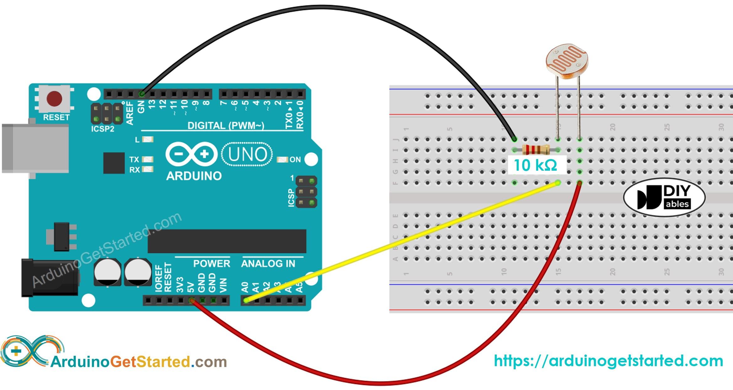
just one modification - I put power to photoresistor from GPIO pin - I suppose there is 3.3v.
All the rest the same - 10K resistor and ADC pin.

I use a lot this circuit with another device - Moteino - I also power photoresitor from GPIO 3.3v - and I receive from photoresistor data via analogRead() function - the values around 750 in my test conditions.

I noticed that on AB-01 boards ver 1.2 when you read ADC with connected photoresistor in this standard circuit - it shows data which much differ - values around 3500.
So again - same circuit, same components, just different device - and analogRead function show different data.
code pretty simple:

#include "LoRaWan_APP.h"
// light sensor >>>>>>>>>>>>>>>>>>>>>>>>>>>>>>>>>>>>>>>>>>>>>>>
//HTCC-AB01
//https://github.com/HelTecAutomation/CubeCell-Arduino/blob/master/variants/CubeCell-Board/pins_arduino.h

#define LIGHT_PWR P0_2 // GPIO0
#define LIGHT P2_3 // ADC
// light sensor <<<<<<<<<<<<<<<<<<<<<<<<<<<<<<<<<<<<<<<<<<<<<<<

void setup()
{
    Serial.begin(9600);
    pinMode(LIGHT_PWR, OUTPUT);
        digitalWrite(LIGHT_PWR, LOW);
    pinMode(LIGHT, INPUT);
}

void loop() {
  digitalWrite(LIGHT_PWR, HIGH);
  int light = analogRead(LIGHT);
  Serial.print(F("light: ")); Serial.println(light);
  digitalWrite(LIGHT_PWR, LOW);
  delay(2000);
}

and I can see in output:

light: 3438
light: 3371
light: 3584
light: 3559
light: 3753
light: 3521

is it normal behavior and I should just consider to take this in mind and correct my code for CubeCells boards? or Im doing something wrong while reading analog values from ADC pin this way?

The readings you get from ADCs on different platforms will invariably depend on the sensitivity (the maximum voltage that can be measured) and resolution (the range of reported values) of the respective ADCs. The ADC on the CubeCell ASR6502 processor has 12 bit (0…4095) resolution and accepts a maximum voltage of 2.4V—higher voltages can be measured using an appropriate voltage divider on the input.

thank you.
As I found out - on my Moteino devices - it is 10bit ADC with 0-1023 values.
So seems in my case its better to calibrate new results of values from Cubecell.

and is it means that my circuit with 10K resistor also wrong for using with Cubecell? because I power this photoresistor from GPIO1

#define LIGHT_PWR P6_1 // GPIO1

which has 3.3v but I need max 2.4?

No, you just need a voltage divider to scale down the value to a maximum of 2.4V

Without knowing the values of the LDR it’s not possible to do any calculations.

thanks… can you also advice how to do it? on “arduino” devices I use the circuit like on first message, but seems I need change it to use on Cubecell?
as far I understand - this resistor 10K and LDR(photoresistor) - form a voltage divider, right? but I need change nominal or resistor to fit it to Cubeell ADC requirement of 2.4v?

Which bit of:

passed you by?

lost in translation ©
I use LDR GL5516 which is 5-10K bright resistance according to aliexpress item page.

“chatgpt” told me to do like this:
edit - PNG was wrong.
never use chatgpt)

You’ve got to keep the old adage “Garbage In Garbage Out” in mind when you’re dealing with computers in general, and ChatGPT is no exception… That circuit looks like nonsense to me…

Going back to your original CubeCell output, there’s nothing inherently wrong with a CubeCell ADC reading in the range 0~4095. If the readings don’t exceed 4095, which will mean that you’re not reading a voltage of more than 2.4V on the ADC pin, that side of things is fine. All you need to do is calibrate your output appropriately.

so my old circuit from first message is ok? only one 10K resistor and LRD and power from 3.3v pin.

but how can it exceed 4095 - this is the maximum value for reading a 12-bit ADC, isn’t it?

Probably, but if your LDR gets a particularly strong light and drops to 3K8, then it will max out the ADC.

And from prior experience of LDR’s, they don’t always stick to the spec sheets (because they can’t read).

If you are in a normally lit room you could just try it and see …

Yes, a wording problem on my part.

should really have been:

If your readings are always less than 4095,

Following @nmcc’s comment:

the normal ‘thorough’ approach would have been to choose a resistor value (where you have the 10kΩ resistor, and 10kΩ may be just fine, but without knowing the characteristics of the LDR we can’t know for sure) that, when combined with the LDR, would create a voltage divider that would deliver a maximum voltage of 2.4V to the ADC pin. Then, if your application never generated anything like 2.4V at the ADC pin in that configuration, you could vary (decrease) the resistor value to generate readings that maxed out closer to 2.4V. But you’d probably only do that if you really felt a need to take advantage of the full ADC resolution.

A quick scan of the PSoC 4000 data sheet indicates that it can operate with a supply voltage (VDD) in the range 1.8~5.5V and that the maximum voltage that can be tolerated on a GPIO Pin is VDD+0.5V. I don’t know how that translates to the CubeCell implementation, but if I’m not overlooking something [very important] it suggests that the GPIO pins on the CubeCell might well be able to handle up to 6V, regardless of the limits of the ADC, which would then just max out at 4095 for anything over 2.4V. But I’m not confident enough in my interpretation of these data to hit one of my CubeCells with a 6V signal just to find out if it can handle it…

EDIT: I’ve just found a datasheet for the ASR6501 and it lists the absolute max supply voltage, for the MCU at least, as 3.9V, so hitting those CubeCell GPIO/ADC pins with anything much more than that might not be such a good idea…