Warning regarding cubecell capsule

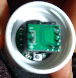
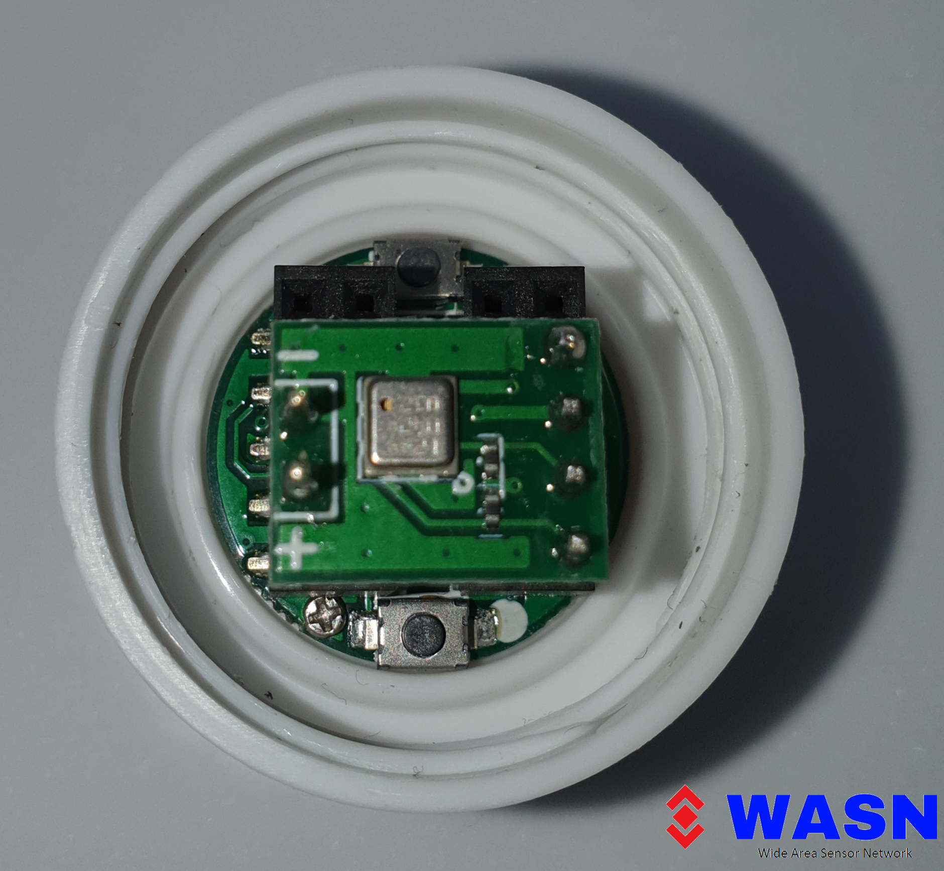
I have written this warning as BEFORE anyone uses a CubeCell capsule. They should be aware that the GITHUB and Heltec Site Diagram of the PINOUT currently does not show clearly the correct orientation . So the sensor can be placed wrongly if you look at the actual capsule and the diagram. The diagrams should have a White spot which is next to the RST button to indicated the correct orientation of the connection block.

For information my Capsule has come with:

  • SENSOR INCORRECTLY FITTED . I had to seek help from GipsyBlue for his connection on his sensors. Not sure what damage that has done.
  • MY CAPSULE HAD BATTERY FITTED AND WAS TOTALLY FLAT . Not good for any battery. Very large current draw when 5v added to “vs” connection to try to recover it.
  • NO USB INTERFACE BOARD SUPPLIED – so cannot program

HELTEC ACTION :

  • Need to urgently amend drawing on this site and GitHub, so white dot shown and clearly mark where sensor are connected to prevent errors. As in my case sensor put in wrong at production of Distributor.
  • Make use that all capsule orders have a USB interface board to program them and make clear to dealers and distributor’s this fact and make clear in sale material that the unit is supplied with board to program.
  • Batteries in products while good, need to be able to not run flat and discharge beyond the safe point. Add a system to disable battery or allow the user to plug in battery when they configure.
  • For me replace the unit and sensor with one that is working and can be programmed.

Heltec make good product like the CubeCell Board but the above lets down a good product and I would not buy again if it come in this state.

Simon

I Think you have not bought the capsule directly from heltec.
All capsules i have bought came without a battery like stated from heltec and with the sensor correctly connected. Each order came with one usb board.

You are right that There should be a better documentation.

The pinout Diagramm of the capsule is on github

https://github.com/HelTecAutomation/ASR650x-Arduino/blob/master/PinoutDiagram/HTCC-AC01.pdf

And linked on the website:

On that Diagramm the white dot is not been because the pcb was mounted on the other site of the enclosure. Now the pcb is mounted right and you can see the Pcb when opening the Transparent cap. The dot is now right beside the reset Button and clearly visible.
On the usb board There is a white dot top. Just alugn them before plugging all together.

I have not soldered the battery directly on the Pcb.
I have soldered short leads with a plug for the 100mAh Batteries i use. I Think this is a better was and you can easily change the battery when needed.

I purchased 5 CubeCell capsules directly from Heltec but only one USB board was shipped with my order
I had to talk to you @rsmedia before I could identify the USB board.

How many boards does one have to purchase to receive a USB board with an order? This type of inconsistency is just not acceptable - especially when @Supporter knew that the USB board was needed to be able to connect a PC/Mac to it. No gift policy is displayed on the Heltec website and I expect that in my next order, @hunter8801will arrange to have the 4 pcs I was denied replaced for free- irrespective of the fact that now the board is being displayed as being publicly available for sale!

Also re battery installation inside the capsule, over 30+years of hand on engineering experience tells me that is TROUBLE waiting to kill the sales of the capsule product. I did suggest to @Supporter to do exactly what @rsmedia is saying as a default. There should be a short battery wire be FACTORY installed so that when one is lucky to find the recommended battery, all you have to do is just plug it in! Dismantling a product like the capsule and soldering a lead in there is just disaster waiting to happen

BTW the correct URL for the Capsule pin out is
https://github.com/HelTecAutomation/ASR650x-Arduino/blob/master/PinoutDiagram/HTCC-AC01.pdf

Hope my documentation make it a little Bit clearer

Hi yes it does for connecting board to capsule (if I had one) but Ali need to be clear about how the sensors are plugged in as they can be place in wrong like mine. Picture is need showing sensor plugged in near white dot. Simon

My CubeCell purchased from Heltec arrived yesterday with the MPU9250 installed as depicted in this photo: MPU9250

There’s no white dot on the sensor itself but instead it’s on the board underneath the headers to which the sensor was attached… In the bottom right corner of the capsule contents in the photo here, just to the right of the little (reset?) button. I removed the sensor to place the USB board pins in the headers with the white dot in the USB board facing the one next to the reset button.
The configurator then seemed to run fine to update firmware… but I am confused/lost in the configurator instructions here:

  1. Login to TTN and create a new device. Get your keys from TTN.
  2. Select your COM Port and click connect.
  3. Keys and DutyCycle are read from the CubeCell device.
  4. Type in your Keys and DutyCycle.
  5. Click on Write

Step one and two seem complete… In step 3, “Keys” refer to the DevEUI, AppEUI and AppKey from TTN? Those I can type in according to step 4. But how do I determine what to enter in regard to DutyCycle? Thanks for any advice.

A different sensor, but similarly positioned, and much clearer view, in this raystream photo, of the white dot to the right of the button underneath:

Hi

keyss = DevEUI, AppEUI, AppKey
DutyCycle = the time between sends, just type it in the fields,
example for all 15 minutes, hour: 0, Minute: 15, Seconds: 0

1 Like

Thanks!
And then, since I don’t have a battery, would I plug the sensor into the USB board that is attached to the CubeCell? And, if so, should I then see a change in the “Never Seen” status at the Things Network Console? Or would I need to do something via an Arduino IDE first?
BTW, do you have any plans to sell CubeCells, with battery connector included, to the USA?

yes you can plug the sensor in the USB board, all pins are path through.
If you use the Configurator to flash the firmware and enter the keys you do not need the arduino ide.

just flash it, type in your “keys” and it should go “online”

We just in the startup phase of our little company and only selling to Europe.
Selling to other countries will be starting in the first quarter of 2020

Ah, that’s helpful.
It seems I am able to flash the firmware successfully. Does it matter whether or not a sensor is plugged into the USB board at that stage of the process?

And then I can enter the keys from TTN and apparently write them and a 0, 15, 0 duty cycle successfully to the device. But TTN nevertheless reports the device as “Never Seen”.

And the WIndows 10 device manager states: “Unknown USB Device
Windows has stopped this device because it has reported problems. (Code 43)
A request for the USB device descriptor failed.”

Is there something else I should hope to see for the device in Windows device manager?

you should see a serial com port device.
have you selected the right com port before flashing?

The only option in the Configurator’s drop down menu was “COM1” so that’s what I selected.

And the only port listed in device manager under Ports when I view devices by “type” is: “Communications Port (COM1)”

There’s no error when I select Connect in the Configurator… That switches to provide a “Disconnect” option

if it is the right com port and you click connect the fields for the “keys” should be filled with the active data.
if these field are empty after connect it was the wrong com port.

you said you see a unknown usb device. if you disconnect the Capsule is it still there?
if not you have to search for the right driver.
sometime using an other usb cable works if the driver is installed but did not find the board

As you suggested, I tried another USB cable and instead of a “not recognized” USB in device manager I then saw
CP2102 USB to UART Bridge Controller

There was a triangle with exclamation mark and the explanation
“The drivers for this device are not installed.”
“There are no compatible drivers for this device.”

Update driver didn’t find an appropriate driver… but I installed a driver from here
https://www.silabs.com/products/development-tools/software/usb-to-uart-bridge-vcp-drivers

And the device then showed up in device manager as:
Silicon Labs CP210x USB to UART Bridge (COM7)

When I typed COM7 as the Port in the configurator I was able to successfully flash the firmware, write the keys, etc.

And shortly thereafter saw a join request and accept in the TTN console (the sensor was already connected to the USB board)…

And traffic seems now to be flowing. Thank you so much!!

Great that it is working now.